background image

TROUBLESHOOTING

I am unable to access the web-based configuration utility:

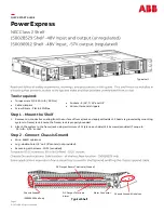
Check that you are using the correct IP address to access the panel by pressing the 

Output Select

     button on the front of the panel to view the 

Network Status

 screen on the LCD. The IP address for

     the panel may have changed if DHCP is enabled.  

If the 

Network Status

 screen on the LCD shows 

Network Not Connected

, check the network cable 

     connections to the panel and the network.

Ensure that you are using the correct type of network cable.  An industry standard "crossover" cable

     should be used for connecting directly to a computer, and a “straight-through” cable should be used
     for connecting to a network. 

Ensure the network card settings on your computer are appropriate for accessing the IP address of the

     panel. To access a panel wtih the default IP address of 192.168.0.180, typical network settings for 
     your computer are:
 o 


IP Address:

 192.168.0.100

 o 


Subnet Mask:

 255.255.255.0

 o 


Gateway:

 192.168.0.1

If the HTTP port of the panel has been changed, you must append the port number to the URL used to

     access the panel. See the

 Password Reset

 section for instructions on how to reset the port number

     to the default setting.

If your network switch allows you to manually configure port speed and duplex settings, turn on

     “Auto-negotiation” on the switch port that the panel is connected to. 

I forgot my password:

See the 

Password Reset

 section for instructions on how to reset the password.

I am not receiving e-mails from the panel:

On the 

Network Setup

 page, ensure that the 

SMTP Server

 field is entered correctly.  The 

SMTP Port

     should be set to 

25

 for most servers. 

If your SMTP server requires SSL encrytion, ensure that the 

SMTP Server requires SSL

 checkbox is

    checked. Otherwise, this box must be left unchecked.

If your SMTP server requires authentication, ensure that the 

SMTP User Name

 and 

SMTP Password 

    fields are entered correctly.  If no authentication is required, leave these fields blank.

Verify your e-mail settings by going to the

 Maintenance

 page and clicking on the 

Send Test E-mail


     button to send a test e-mail. The 

Send Test E-mail

 page will display an error message if the panel

     unable to send the e-mail.

On the setup pages, ensure that the 

Send E-mail

 checkboxes are checked for alarm conditions you

     wish to receive notifications for.

24

Summary of Contents for ICT180S-12B

Page 1: ...855 313 077 The Power of Reliability INSTRUCTION MANUAL ICT DISTRIBUTION SERIES 2 DC Load Distribution Panel ICT180S 12B INTELLIGENT MODEL WITH REMOTE MONITORING INNOVATIVE CIRCUIT TECHNOLOGY LTD...

Page 2: ...tatus Page 10 Device Setup Page 11 Output Setup Page 12 Network Setup Page 13 E mail Setup Page 15 Alarm Setup Page 16 User Setup Page 18 Maintenance Page 19 Mobile Web App Page 20 Text Message Alarm...

Page 3: ...nd insert fuses fully 4No internal user serviceable parts Refer all product service to an authorized ICT Ltd service facility CAUTION Risk of personal injury or damage to equipment Always observe the...

Page 4: ...for monitoring alarms generated by the panel Remote monitoring is available through the integrated security protected Ethernet communications port on the back of the panel The panel has a built in web...

Page 5: ...s INSTALLATION 1 Inspect panel and accessories to make sure everything is complete and in good condition 2 For rack set up install panel on the rack using appropriate size screws and star washers on a...

Page 6: ...cable for Ethernet connection is Cat5e UTP network cable 8 The Alarm Form C Contacts on the back of the panel can be connected to an external alarm circuit to monitor alarms generated by the panel Dep...

Page 7: ...ked and no fault occurred System Over Voltage Alarm System Over Current Alarm All Activate Alarm Form C Contact is not checked No power to unit Alarm Input 1 5 Activate Alarm Form C Contact is checked...

Page 8: ...or screen order Figure 3 LCD Screens 7 Holding the Output Select button for 2 seconds at any screens will return you to the main screen Holding the Output Select button for 20 seconds at any screens w...

Page 9: ...sed configuration utility Line 2 Displays the fuse status OK for good fuse and OPEN for blown fuse Line 3 Displays the output voltage Voltage display will blink if the voltage exceeds the Under Voltag...

Page 10: ...ddress field of the browser If the panel is connected to a network with a DHCP server the panel will be assigned an IP address automatically To find the current IP address of the panel see the LCD Ope...

Page 11: ...rowser window STATUS This page provides information on system voltage system current fuse status current level by output contact 1 through 12 and alarm status If any alarm inputs are enabled the statu...

Page 12: ...r A valid server address must also be entered in the NTP Server field NTP Server The name or IP address of the NTP Server used for date and time synchronization such as pool ntp org Time Zone Select a...

Page 13: ...o 0 Amps Activate Alarm Form C Contact If this box is checked the Alarm Form C Contacts on the panel will indicate a fault condition when the over current alarm is triggered for the selected output Se...

Page 14: ...ry DNS Server for your network Secondary DNS Specify the IP address of the Secondary DNS Server for your network WEB SERVER WARNING Changing these ports may affect your ability to access the panel The...

Page 15: ...ts through SNMP If this box is unchecked all information available from the SNMP agent will be read only SNMP Contact Information Assign contact information such as an operator name and phone number f...

Page 16: ...s field can also be used to send a text message notification to a cell phone See the Text Message Alarm Notifications section for more information SMTP User Name If your SMTP server requires a user na...

Page 17: ...e alarm will clear The value in this field must be at least 0 50V higher then the Under Voltage Threshold Activate Alarm Form C Contact If this box is checked the Alarm Form C Contacts on the panel wi...

Page 18: ...etup page must be configured correctly before e mail notifications can be sent ALARM INPUT 1 5 Alarm Name Allows you to assign a custom name to each individual alarm input Contact Type Allows you to c...

Page 19: ...eturn the password to the default setting See the Password Reset section for more information Select a User to Edit There are two user accounts with access to the panel Administrator user name admin T...

Page 20: ...TORY DEFAULT SETTINGS Pressing the Restore button will restore ALL settings to the original factory default values including the passwords If you only want to restore the network settings and password...

Page 21: ...current alarm input status fuse status and current level by output contact 1 through 12 TEXT MESSAGE ALARM NOTIFICATIONS The panel can send text message alarm notifications to a cell phone by sending...

Page 22: ...ding screen In the Linksys WRT54G this is located in the Applications and Gaming tab The location of port forwarding may be different on other routers consult your router manual for instructions 2 To...

Page 23: ...eat steps 2a 2e with the HTTPS port number that the panel is using If you are using the default panel port settings the HTTPS port number is 443 4 To set up your router to allow remote panel firmware...

Page 24: ...ype the WAN IP Address of the router in the location address field of your browser followed by a colon and the HTTP port number that the panel is using e g http 209 123 10 33 8000 for IP Address 209 1...

Page 25: ...he URL used to access the panel See the Password Reset section for instructions on how to reset the port number to the default setting If your network switch allows you to manually configure port spee...

Page 26: ...ut fuse 60mV Typical Alarm Form C Contact Form C Dry Contacts 1A 60VDC Max Alarm Sensor Inputs External dry contact alarm inputs configurable for NO or NC logic Applied voltage 3 3V 0 4mA for contact...

Page 27: ...he parties Products shipped to ICT which have incurred freight damage will not be covered by this Warranty and any repairs or replacement parts components or products needed will be invoiced in the fu...

Reviews: