


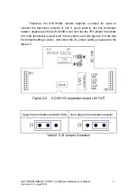
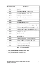


AO Max. AO a n
*1 *2
Send status command to n
th
CANopen
slave. (write only)
*6
AO Max. AO a N + 1
*3
Reset the GW-7433D. (write only)
*7
AO Max. AO a N + 2
*3
Set the GW-7433D to “Listen Mode”
*8
Table 4-3:
Special
Data Addressing
*1: The Max. AI/AO address is decided by the maximum AI/AO channels
configuration by utility.
For example, if users finish the configuration by the
GW-7433D utility, check the mapping table and find that there are 8 AI data
(16-bytes) assigned in the Modbus memory, the Max. AI address is 0007h (or
30008h for PLC) because the useful AI channel is from 0 ~ 7.
*2:
“n” is the CANopen slave device number. The number range is 1 ~ 10.
*3:
“N” is the total CANopen slave device amount.
*4:
About the error status, please refer to the table 2-6.
*5:
About the CAN status, please refer to the table 3-1.
*6:
GW-7433D can send status command to CANopen slave through this
address (Max. AO a n).
Write 0x01 to this address will let the relative
CANopen slave into “Operational mode” status, write 0x02 to into “Stop mode”
status, write 0x80 to into “Pre-operational mode” status and write 0x81 to reset
this CANopen slave.
*7:
Writing the address (Max. AO a N + 1) to 1 will let the GW-7433D
reboot.
*8:
Writing the address (Max. AO a N + 2) to 1 will let the GW-7433D
into listen mode. If users want to recover to the normal mode, please write it to
0. About the details of “Listen Mode”, please refer to
section 3.3.
GW-7433D MODBUS TCP/RTU to CANopen Gateway User Manual
27
(Version 2.1.0, Aug/2019)