441 01 2314 06
Specifications are subject to change without notice.
23
10. Checks and Adjustments
Startup
NOTE:
Refer to startup procedures in the
Users Information
Manual
.
!
ELECTRICAL SHOCK, FIRE, OR EXPLOSION
HAZARD
Failure to follow this warning could result in personal
injury, death and/or property damage.
If any sparks, odors or unusual noises occur,
immediately shut OFF gas and power to furnace.
Check for wiring errors or obstruction to blower.
WARNING
Gas Supply Pressure
Gas supply pressure should be within minimum and maximum val-
ues listed on rating plate. Pressures are usually set by gas suppli-
ers.
(See Propane Gas Conversion Kit instruction manual for furnaces
converted to Propane gas)
Manifold Gas Pressure Adjustment
NOTE:
Make adjustment to manifold pressure with burners oper-
ating.
!
FIRE OR EXPLOSION HAZARD
Failure to follow this warning could result in personal
injury, death and/or property damage.
Turn OFF gas at shut off before connecting
manometer.
WARNING
1. With gas
OFF
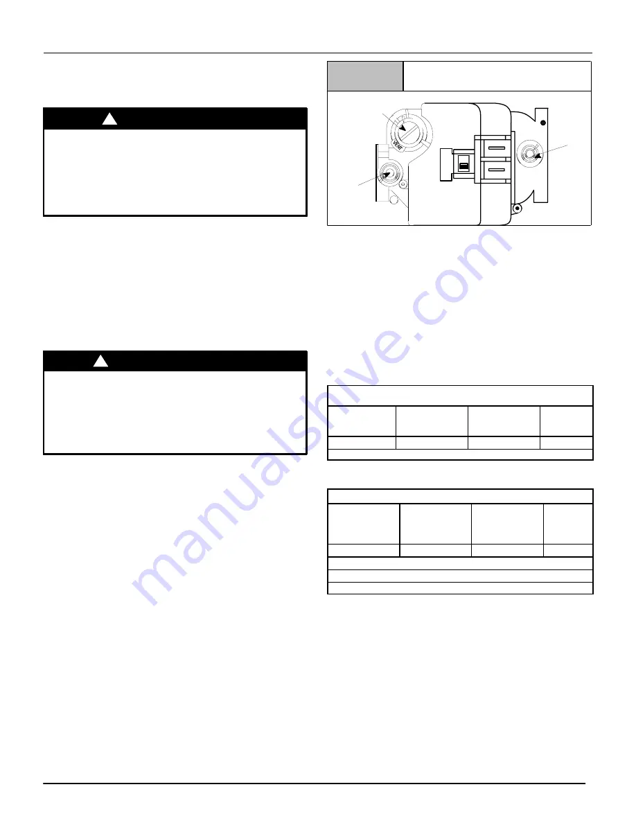
, connect manometer to manifold pressure tap
on outlet of gas control valve. See
Figure 19
. Use a manome-
ter with a 0 to 12 in wc (0 to 3014 Pa) range.
2. Turn gas
ON.
Operate the furnace by using a jumper wire on
the R to W thermostat connections on the control.
3. Remove manifold pressure adjustment screw cap on furnace
gas control valve. Turn adjusting screw using 3/32 hex
wrench, counterclockwise to decrease manifold pressure and
clockwise to increase pressure. See
Figure 19
.
NOTE:
Adjustment screw cover
MUST
be replaced on gas control
valve before reading manifold pressure and operating furnace.
4. Set manifold pressure to value shown in
Table 5
or
Table 6
.
5. When the manifold pressure is properly set, replace the adjust-
ment screw cover on the gas valve.
6. Remove jumper wire from thermostat connection on control.
Remove manometer connection from manifold pressure tap,
and replace plug in gas valve.
7. Check for leaks at plug.
Typical Gas Control Valve
Figure 19
Regulator Adjustment
Under Cap
Inlet
Pressure
Tap
1
/
8
NPT
INLET
OUTLET
Outlet
Pressure
Tap
1
/
8
NPT
IN
OF
F
ON
HONEYWELL
(3.2mm)
(3.2mm)
Natural Gas Input Rating Check
The gas meter can be used to measure input to furnace.
Check with gas supplier for actual BTU content.
1. Turn
OFF
gas supply to all appliances other than furnace and
start furnace. Use jumper wire on
R
to
W.
2. Time how many seconds it takes the smallest dial on the gas
meter to make one complete revolution.
Note:
If meter uses a 2 cubic foot dial, divide results (seconds) by
two.
Refer to
Example.
The Example is based on a natural gas BTU
content of 1,000 BTU’s per cubic foot.
Example (BTUH)
Natural Gas
BTU Content
per cu. foot
No. of Seconds
Per Hour
Time Per Cubic
Foot in
Seconds
BTU Per
Hour
1,000
3,600
48
75,000
1,000 x 3,600
÷
48 = 75,000 BTUH
To Determine the appliance kW input rate from a .05m
3
test dial
that has been clocked at 80 seconds for one complete revolution.
Example (kW)
Number of
seconds per
hour
Number of
seconds per
complete
rotation
Size of test dial
(.05m
3
)
kW
m
3
/h
3,600
80
.05
2.25
3,600
÷
80 x .05 = 7.2 m
3
/h
2.25m
3
/h x 10.35 kWh/m
3
= 23.28 kW
23.28 x 3.412
= 79,431 BTU
3. Remove jumper wire from
R
to
W
.
4. Relight all appliances and ensure all pilots are operating.
Orifice Sizing
NOTE:
Factory sized orifices for natural and Propane gas are
listed in the furnace Technical Support Manual.
Ensure furnace is equipped with the correct main burner orifices.
Refer to
Table 5
or
Table 6
for correct orifice size and manifold
pressure for a given heating value and specific gravity for natural
and propane gas.
Operation Above 2000
′
(610m) Altitude
These furnace may be used at full input rating when installed at al-
titudes up to 2000
′
(610m). When installed above 2000
′
(610m),
the input must be decreased 2% (natural gas) or 4% (Propane
gas) for each 1000
′
(305m) above sea level in the USA. In Canada,


