


12
9. After all the set up procedures mentioned above have
been completed, the burner should be fired and an
inspection mirror should be used to observe the flame
pattern at the tip of the nozzle. Any irregularities such as
burning to one side or pulsating flame patterns should
be corrected by changing the nozzle.
2.3)
FAN ADJUSTMENT CHECK
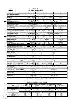
Adjust the fan speed ACCORDING TO THE OIL INPUT
SELECTED, so that the temperature rise is within the one
specified on the Rating Plate (see Table 3). Consult the
wiring diagram for speed changes on the direct drive motor.
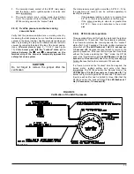
To adjust the fan “OFF” time, set the DIP switches on the
control board to the desired timing as per Figure 9.
FIGURE 9
Adjustment of “OFF” settings
2.4)
LIMIT CONTROL CHECK
After the furnace has been in operation for at least 15
minutes, restrict the return air supply by blocking the filters or
closing the return registers and allow the furnace to shut
down on High Limit. The burner will shut OFF but the main
blower should continue to run.
Remove the restriction and the burner should come back on
in a few minutes.
2.5)
Year round air conditioning
The furnace is designed for use in conjunction with cooling
equipment, to provide year round air conditioning. The
blower has been sized for both heating and cooling,
however, the fan motor speed may need to be changed to
obtain the necessary cooling airflow.
2.6) Heating
The blower speed is factory set to deliver the required airflow
at normal duct static pressure.
2.7) Cooling
The blower speed may be adjusted in the field to deliver the
required airflow for cooling applications, as outlined in
Table 4.
2.8)
Constant Blower Switch
This furnace is equipped with a constant low speed blower
option. Whenever the room thermostat is not calling for
heating or cooling, the blower will run on low speed in order
to provide air circulation. If this constant blower option is not
desired, the rocker switch on the side of the control box can
be used to turn it off.
2.9)
SEALED COMBUSTION SYSTEM (SCS)
OPERATION
2.9.1) General
Note: Refer to the wiring diagrams, Figures 12.7 and 12.8
and the Parts List.
Normal operation
When the thermostat calls for heat, the T-T contact of the
burner Primary Control closes. After a 3 second delay, the
burner motor and igniter are activated by the Primary
Control. After a further 15 second delay the solenoid valve is
activated and ignition occurs.
When the burner blower starts, pressure is created in the
combustion chamber and a vacuum is created in the burner
casing. These pressures act on the PS-1 pressure switch
adjusted to close at 0.8” W.C.. It is important to know that the
two pressures act in the same way on the pressure switch
diaphragm.
In less than 4 seconds, the total pressure
should stabilize between 0.2" and 0.7" W.C. (see section
2.5.2).
Abnormal operation
A Sealed combustion system (SCS) incorporates a safety
shutdown feature that will shut the burner down in the
eventuality of a blocked intake or a blocked vent outlet:
1. The pressure switch PS-1 reacts if the total pressure
goes over 0.8" W.C.;
2. The TDR-1 contact closes after 4 seconds and power is
applied to the C coil of the SPDT relay;
Note:
At that point the L-1 light comes on, which is an
indication that there is a problem with the
pressure in the SCS or with the pressure
switches.
1 2 1 2 1 2 1
60 Sec. 90 Sec. 120 Sec. 150
BOUTONS
1 2
1 2
1 2
1 2
60 Sec.
90 Sec.
120 Sec.
150 Sec.
DIP switches
DNS-0377 Rev. A
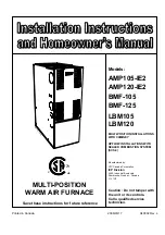
Summary of Contents for AMP105-IE2
Page 20: ...FIGURE 12 1 Diagramme lectrique AMP LBM BMF 075 090 et 105 br leur Beckett 21...
Page 21: ...FIGURE 12 2 Diagramme lectrique AMP LBM BMF 120 140 et 155 br leur Beckett 22...
Page 22: ...FIGURE 12 3 Diagramme lectrique AMP LBM BMF 075 090 et 105 br leur Riello 23...
Page 23: ...FIGURE 12 4 Diagramme lectrique AMP LBM BMF 120 140 et 155 br leur Riello 24...
Page 26: ...FIGURE 12 7 Diagramme lectrique AMP LBM BMF 075 090 et 105 br leur B SCS 27...
Page 27: ...FIGURE 12 8 Diagramme lectrique AMP LBM BMF 120 140 et 155 br leur B SCS 28...
Page 28: ...29 COMPOSANTES ET PI CES DE REMPLACEMENT...
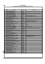
Page 29: ...LISTE DE PI CES Code de fabrication AMP LBM BMF 075 090 105 30 B50058A...
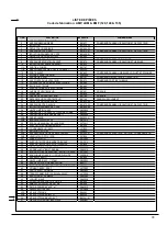
Page 31: ...LISTE DE PI CES Code de fabrication AMP LBM BMF 120 140 155 32 50062A...
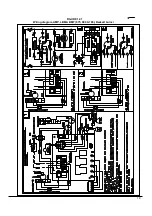
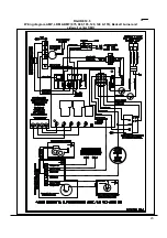
Page 51: ...19 FIGURE 12 1 Wiring diagram AMP LBM BMF 075 090 105 Beckett burner...
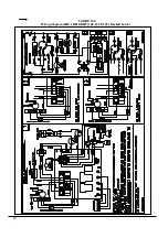
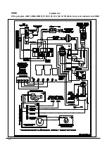
Page 52: ...20 FIGURE 12 2 Wiring diagram AMP LBM BMF 120 140 155 Beckett burner...
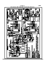
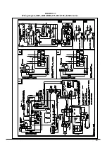
Page 53: ...21 FIGURE 12 3 Wiring diagram AMP LBM BMF 075 090 105 Riello burner...
Page 54: ...22 FIGURE 12 4 Wiring diagram AMP LBM BMF 120 140 155 Riello burner...
Page 57: ...FIGURE 12 7 Wiring diagram AMP LBM BMF 075 090 105 B SCS burner 25...
Page 58: ...FIGURE 12 8 Wiring diagram AMP LBM BMF 120 140 155 B SCS burner 26...
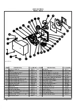
Page 59: ...27 COMPONENTS AND REPLACEMENT PARTS...
Page 60: ...PARTS LIST Model AMP LBM BMF 075 090 105 28 B50058A...
Page 62: ...PARTS LIST Model AMP LBM BMF 120 140 155 30 B50062A...


