ICP AMP105-IE2 Installation Instructions And Homeowner'S Manual Download Page 37


5

When installed in a horizontal position, the furnace may be 
suspended by using an angle iron frame, as long as the total 
weight of both the furnace and the frame are included in the 
calculations. Other methods of suspension are acceptable. 
When installed in the horizontal position, this furnace must 
not be installed on combustible flooring, unless the approved 
sub-base is used (Model # HFB-101). 
 

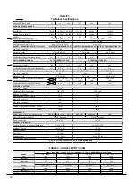
The required minimum clearances for this furnace in all 
positions are specified in Tables 5.1 and 5.2. 


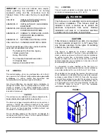
The furnace should be located as closely as possible to the 
chimney or vent in order to keep vent connections short and 
direct. The furnace should also be located near the centre of 
the air distribution system. 
 

1.3.1)  Air for combustion and ventilation


Chimney and SCS installation 

 
Refer to the CAN/CSA-B139 Installation Code for complete 
regulations and for guidance on retrofit applications. 
 
This furnace should be installed in a location in which the 
facilities for ventilation permit satisfactory combustion of oil, 
proper venting and the maintenance of ambient 
temperatures at safe limits under normal conditions of use. 
The location should not interfere with the proper circulation of 
air within the confined space. 
 
When this furnace is installed in a closet or similar enclosure, 
2 ventilation openings are required for combustion air. The 
openings should be located about  152.4 mm (6

")

  from the 

top and the bottom of the enclosure at the front of the 
furnace. Table 1 indicates the minimum dimensions required 
for these ventilation openings. 
 

TABLE 1 

Input 

(BTU/h) 

Width  

Height 

75,000 – 105,000 

0.46 m (18") 

0.20 m (8") 

120,000 – 155,000 

0.51 m (20") 

0.25 m (10") 


WARNING 


Do not block the combustion air openings in the 
furnace. Any blockage will result in improper 
combustion and may result

 in a fire hazard 

and/or cause bodily harm. 


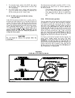
Chimney installation only 

 
The barometric draft regulator included with the furnace, 
shall be installed in the same room or enclosure as the 
furnace, in such a manner as to prevent any difference in 
pressure between the regulator and the combustion air 
supply. 

Air requirements for the operation of exhaust fans, kitchen 
ventilation systems, clothes dryers, and fireplaces shall be 
considered in determining the adequacy of the space to 
provide combustion air requirements. 
 
In unconfined spaces, in buildings of conventional frame, 
brick or stone construction, infiltration may be adequate to 
provide air for combustion, ventilation and dilution of flue 
gases. This determination must be made on an individual 
installation basis and must take into consideration the overall 
volume of the unconfined space, the number of windows and 
ventilation openings, the number of doors to the outside, 
internal doors which can close off the unconfined space and 
the overall air tightness of the building construction. 
 
Many new buildings and homes (and older ones that have 
been weatherized must be considered as being tight 
construction and, therefore, infiltration will not be sufficient to 
supply the necessary air for combustion and ventilation. 
 
A building can be considered as being of tight construction 
when: 

a.  Walls and ceilings exposed to the outside have a 

continuous water vapour retarder with a rating of one 
perm or less, openings have gaskets or are sealed 
and/or; 

b.  Weather-stripping has been added on operable windows 

and doors, and/or; 

c.  Caulking or sealant has been applied to areas such as 

joints around window and doorframes, between sole 
plates and floors, between wall-ceiling joints, between 
wall panels, at penetrations for plumbing, electrical and 
fuel lines and at other openings. 


1.3.2) Duct 

recommendations


The proper sizing of warm air ducts is necessary to ensure 
satisfactory furnace operation. Ductwork should be in 
accordance with the latest editions of NFPA-90A (Installation 
of Air Conditioning and Ventilating Systems) and NFPA-90B 
(Warm Air Heating and Air Conditioning Systems) or 
Canadian equivalent. 
 
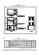
The supply ductwork should be attached to the flanged 
opening provided at the discharge end of the furnace. See 
Figures 11.1 and 11.2 for the dimensions of this opening. 
 
Knockouts are provided on both sides of the furnace to cut 
the required size of opening for the installation of the return 
air ductwork. This can be done on either the right or the left 
side of the furnace. See Table 2 (page 10) for location and 
dimensions. 


NOTE:

  THE BACK SHOULD 

NOT 

BE CUT OUT FOR 

RETURN AIR DUCTING 

 
Also, there is provision on this furnace for a bottom return air 
duct. Knockouts are provided in the floor of the furnace to 
facilitate the cut-out requirement for the air filter rack and 
return ductwork. (We recommend the use of this opening for 
horizontal and counterflow installations). 

Summary of Contents for AMP105-IE2

Page 1: ...ntr les Appeler un technicien qualifi Mod les AMP105 IE2 AMP120 IE2 BMF 105 BMF 125 LBM105 LBM120 2006 03 17 X40002 Rev L INSTALLATION MULTIPOSITION AVEC CHEMIN E INSTALLATION EN D BIT ASCENDANT AVEC...

Page 2: ...ERTISSEMENT il est utilis pour indiquer les pratiques dangereuses qui peuvent provoquer des dommages corporels et ou mat riels mineurs MISE EN GARDE N utiliser qu avec du mazout 2 maximum Ne pas utili...

Page 3: ...n raccordement un vent de dimensions ad quates La capacit d air de cet appareil de chauffage central est con ue pour permettre le refroidissement du d bit d air Se r f rer au tableau 4 pour conna tre...

Page 4: ...T Ne pas obstruer les ouvertures d air de combustion de l appareil de chauffage central Toute obstruction r sultera en une combustion inad quate et accro t les risques d incendie et ou de dommages cor...

Page 5: ...ble d installer des pales acoustiques rotatives ou d isoler les conduits tel que d crit au point b d Si une seule grille d air est utilis e les conduites entre la grille et l appareil de chauffage cen...

Page 6: ...hemin e de ma onnerie Cet appareil de chauffage central peut tre vacu dans une chemin e de ma onnerie existante Toutefois l appareil de chauffage central ne doit pas tre vacu dans une chemin e vacuant...

Page 7: ...unit et le r gulateur de tirage tel qu indiqu sur les instructions fournies avec le dispositif d arr t anti refoulement Le dispositif d arr t doit aussi faire l objet d un entretien annuel R f rer au...

Page 8: ...refoulement Installation en d bit d air ascendant et vacuation verticale FIGURE4 Arrangement g n ral du syst me anti refoulement Installation en d bit d air ascendant et vacuation horizontale FIGURE...

Page 9: ...e est fix e au tube d air du br leur et aucun ajustement n est requis pour la longueur d insertion AVERTISSEMENT Si le relais de combustion install sur le br leur est de la s rie R7184 de Honeywell NE...

Page 10: ...tiliser TABLEAU 2 Fournaise Mod les Filtre air Dim Ouverture Dim AMP LBM et BMF 075 090 et 105 16 x 24 15 x 23 AMP LBM et BMF 120 140 et 155 18 x 30 17 x 29 1 3 11 Installation l horizontale ou d bit...

Page 11: ...25 W C et 035 W C 4 Pour les installations avec vacuateur mural SCS la pression dans le tuyau d vacuation doit correspondre celle sp cifi e dans les tableaux de sp cifications techniques 5 La pression...

Page 12: ...en fermant les registres de retour d air et laisser l appareil de chauffage central s teindre en limite lev e Le br leur va s teindre OFF et le ventilateur principal devrait continuer fonctionner Enle...

Page 13: ...ecyclage voir section 2 9 3 et fera 3 essais de d marrage Le nombre d essais maximum est de 3 Apr s le contr le R7184 tombe en mode s curit lockout state 2 9 2 V rification de la pression et du vacuum...

Page 14: ...appareil de chauffage central sans filtre air Les filtres jetables devraient tre remplac s au moins une fois par ann e Si l appareil de chauffage central est quip pour la climatisation les filtres dev...

Page 15: ...AVERTISSEMENT Assurez vous que le ventilateur est ad quatement soutenu quand vous le sortez des rails surtout en position horizontale ou en d bit descendant afin d viter d chapper le ventilateur et d...

Page 16: ...sse du technicien de service R SULTAT DU TEST DE MISE EN MARCHE Gicleur Pression lb po 2 Ajustements du br leur Bande principale Bande fine Position de la t te CO2 Indice de fum e Bacharach Temp ratur...

Page 17: ...BE 3 3 8 D flecteur bas r gime NON Disque statique mod le 2 3 4 3383 Gicleur 100 PSIG pression pompe Delavan 0 60 70B 0 65 70B 0 75 70B 0 85 70W 1 00 70W Pression de la pompe PSIG 120 135 130 140 120...

Page 18: ...ALE LA CONDUITEPREMIERS 6 PI 2 2 3 DESSOUS FOURNAISE PLANCHER COMBUSTIBLEAVEC BASE 0 0 0 HORIZONTALE OU SOUS LE TUYAU FUM E 4 4 4 VERTICALE AU DESSUS DU TUYAU FUM E 9 9 9 DEVANT FOURNAISE 8 8 24 C T D...

Page 19: ...ALE LA CONDUITEPREMIERS 6 PI 2 2 3 DESSOUS FOURNAISE PLANCHER COMBUSTIBLEAVEC BASE 0 0 0 HORIZONTALE OU SOUS LE TUYAU FUM E 4 4 4 VERTICALE AU DESSUS DU TUYAU FUM E 9 9 9 DEVANT FOURNAISE 8 8 24 C T D...

Page 20: ...FIGURE 12 1 Diagramme lectrique AMP LBM BMF 075 090 et 105 br leur Beckett 21...

Page 21: ...FIGURE 12 2 Diagramme lectrique AMP LBM BMF 120 140 et 155 br leur Beckett 22...

Page 22: ...FIGURE 12 3 Diagramme lectrique AMP LBM BMF 075 090 et 105 br leur Riello 23...

Page 23: ...FIGURE 12 4 Diagramme lectrique AMP LBM BMF 120 140 et 155 br leur Riello 24...

Page 24: ...FIGURE 12 5 Diagramme lectrique AMP LBM BMF 075 090 105 120 140 et 155 br leur Beckett et vacuateur SMH 25...

Page 25: ...FIGURE 12 6 Diagramme lectrique AMP LBM BMF 075 090 105 120 140 et 155 br leur Riello et vacuateur SMH 26...

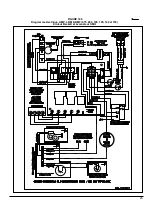
Page 26: ...FIGURE 12 7 Diagramme lectrique AMP LBM BMF 075 090 et 105 br leur B SCS 27...

Page 27: ...FIGURE 12 8 Diagramme lectrique AMP LBM BMF 120 140 et 155 br leur B SCS 28...

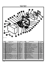
Page 28: ...29 COMPOSANTES ET PI CES DE REMPLACEMENT...

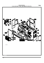
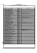
Page 29: ...LISTE DE PI CES Code de fabrication AMP LBM BMF 075 090 105 30 B50058A...

Page 30: ...85 02 COMPREND PANNEAU ISOLATION ET DEFLECTEUR 25 ISOLATION PANNEAU DE COTE B01645 02 26 HAUTE LIMITE 195 30F R02R003 27 GARNITURE COUVERCLE DE TUYAU A FUMEE B01214 28 GARNITURE BRIDE FIXE BECKETT N04...

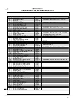
Page 31: ...LISTE DE PI CES Code de fabrication AMP LBM BMF 120 140 155 32 50062A...

Page 32: ...E B01875 02 COMPREND PANNEAU ISOLATION ET DEFLECTEUR 25 ISOLATION PANNEAU DE COTE B01800 02 26 HAUTE LIMITE 175 20F R02R005 27 GARNITURE COUVERCLE TUYAU DE FUMEE B00205 28 GARNITURE BRIDE FIXE BECKETT...

Page 33: ...imentation d huile B02251 7B Isolation urethane bas 3 4 x 17 B01526 80 24 Pompe avec valve soleno de N01Z068 7C Isolation urethane haut 3 4 x 22 1 2 B01526 81 25 Harnais pour bobine N01Z069 8 D tecteu...

Page 34: ...l a qualified service technician Models AMP105 IE2 AMP120 IE2 BMF 105 BMF 125 LBM105 LBM120 2006 03 17 X40002 Rev L MULTI POSITION INSTALLATIONS WITH CHIMNEY UPFLOW INSTALLATIONS WITH SEALED COMBUSTIO...

Page 35: ...esult in death or serious bodily and or material damage CAUTION Hazards or unsafe practices which CAN result in minor bodily and or material damage WARNING For use with grade 2 Fuel Oil maximum Do not...

Page 36: ...and connection to a properly sized vent The air handling capacity of this furnace is designed for cooling as well Refer to Table 4 for the expected airflow at various external static pressures 1 3 LOC...

Page 37: ...to provide combustion air requirements In unconfined spaces in buildings of conventional frame brick or stone construction infiltration may be adequate to provide air for combustion ventilation and d...

Page 38: ...ARNING The coil MUST be installed on the air discharge side of the furnace Under no circumstances should the airflow be such that cooled conditioned air is allowed to pass over the furnace heat exchan...

Page 39: ...h the furnace must be used for the proper functioning Installation instruction are included with the control 1 3 5 BLOCKED VENT SHUT OFF BVSO FOR CHIMNEY VENTING WARNING It is imperative that this dev...

Page 40: ...Blocked Vent Shut Off device wiring Installation Horizontal with vertical exhaust Blocked Vent Shut Off device wiring Installation Upflow with horizontal exhaust FIGURE 4 Blocked Vent Shut Off device...

Page 41: ...ir tube and no adjustment is required for insertion length CAUTION NEVER use the interrupted ignition function if a Honeywell R7184 series combustion relay is installed on the burner Oil Connections C...

Page 42: ...de panel or on the bottom of the furnace to accommodate the return air ductwork A sufficient clearance should be provided for air filter access Refer to Table 2 for filter rack flange dimensions for r...

Page 43: ...the heat exchanger or the flue pipe Refer to the Technical Specifications in this manual for overfire pressure values A high pressure condition may be caused by excessive combustion air due to the air...

Page 44: ...able 4 2 8 Constant Blower Switch This furnace is equipped with a constant low speed blower option Whenever the room thermostat is not calling for heating or cooling the blower will run on low speed i...

Page 45: ...er than 0 8 W C there is an obstruction in the flue pipe If the vacuum reading is close to or greater than 0 8 W C there is an obstruction in the air inlet pipe 2 9 3 R7184 Control operation Three sec...

Page 46: ...exchanger or flue pipe every year but it is advisable to have a qualified service technician check the unit before each heating season to determine whether cleaning or replacement of parts is necessar...

Page 47: ...UTION Do not dent or scratch the surface of the thermal switch If the thermal switch is damaged replacement is required 6 Clear and remove any build up or obstruction inside the heat transfer tube 7 R...

Page 48: ...y for w ire sizing Max w ire lenght ft Max fuse size Amps Control transformer External control pow er available Heating Cooling BLOWER DATA Blow er speed at 0 50 W C static pressure MED LOW MED HIGH H...

Page 49: ...RM AIR DUCT WITHIN 6 ft OF FURNACE 2 2 3 BOTTOM FURNACE COMBUSTIBLEFLOOR WITH SUB BASE 0 0 0 HORIZONTALLY OR BELOW FLUEPIPE 4 4 4 VERTICALLY ABOVEFLUEPIPE 9 9 9 FRONT FURNACE 8 8 24 SIDES TOP FLUEPIPE...

Page 50: ...M AIR DUCT WITHIN 6 ft OF FURNACE 2 2 3 BOTTOM FURNACE COMBUSTIBLEFLOOR WITH THESUB BASE 0 0 0 HORIZONTALLY OR BELOW FLUEPIPE 4 4 4 VERTICALLY ABOVEFLUEPIPE 9 9 9 FRONT FURNACE 8 8 24 SIDES TOP FLUEPI...

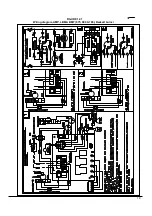
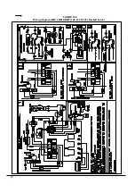
Page 51: ...19 FIGURE 12 1 Wiring diagram AMP LBM BMF 075 090 105 Beckett burner...

Page 52: ...20 FIGURE 12 2 Wiring diagram AMP LBM BMF 120 140 155 Beckett burner...

Page 53: ...21 FIGURE 12 3 Wiring diagram AMP LBM BMF 075 090 105 Riello burner...

Page 54: ...22 FIGURE 12 4 Wiring diagram AMP LBM BMF 120 140 155 Riello burner...

Page 55: ...23 FIGURE 12 5 Wiring diagram AMP LBM BMF 075 090 105 120 140 155 Beckett burner and sidewall venter SMH...

Page 56: ...FIGURE 12 6 Wiring diagram AMP LBM BMF 075 090 105 120 140 155 Riello burner and sidewall venter SMH 24...

Page 57: ...FIGURE 12 7 Wiring diagram AMP LBM BMF 075 090 105 B SCS burner 25...

Page 58: ...FIGURE 12 8 Wiring diagram AMP LBM BMF 120 140 155 B SCS burner 26...

Page 59: ...27 COMPONENTS AND REPLACEMENT PARTS...

Page 60: ...PARTS LIST Model AMP LBM BMF 075 090 105 28 B50058A...

Page 61: ...H BECKETT N04Z026 29A BURNER ASSEMBLY B03091 01 29B BURNER RIELLO 40 F3 N01F011 30 HEXAGONAL NUT 3 8 16NC ZINC F07F011 31 CAPACITOR HOLDER B01024 32 CAPACITOR 5 MF L01I001 33 MOTOR SUPPORT ASSEMBLY 1...

Page 62: ...PARTS LIST Model AMP LBM BMF 120 140 155 30 B50062A...

Page 63: ...TION AND BAFFLE 25 INSULATION LEFT SIDE PANEL B01800 02 26 HIGH LIMIT 175 20F R02R005 27 GASKET SMOKE BOX COVER B00205 28 GASKET FIXED BREECH BECKETT N04Z026 29A BURNER ASSEMBLY B03092 01 29B BURNER R...

Page 64: ...ine B02251 7B Urethane gasket 3 4 x 17 top B01526 80 24 Pump w ith solenoid valve N01Z068 7C Urethane gasket 3 4 x 22 1 2 bottom B01526 81 25 Wiring harness N01Z069 8 Pressure sw itch R99F022 26 Elect...

Reviews: