


9
1.3.6) AIR INLET AND FLUE OUTLET PIPE
PROTECTION
(Sealed Combustion Systems only)
Install pipe protection at air inlet and flue outlet locations, as
shown in Figure 8.
FIGURE 8
Pipe protection installation (SCS only)
1.3.7) Venting instructions
(Sealed Combustion Systems)
Refer to the SCS-4 Instruction Manual.
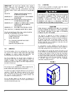
1.3.8) Oil
burner
This furnace is equipped with a high pressure atomizing
retention head type burner for use with not heavier than
grade 2 Fuel Oil. The mounting flange is fixed to the burner
air tube and no adjustment is required for insertion length.
CAUTION
NEVER
use the “interrupted ignition” function if a
Honeywell R7184 series combustion relay is
installed on the burner.
Oil Connections
Complete instructions for installation of the fuel oil piping will
be found in the oil burner installation instructions included
with the furnace.
Oil line entry holes are located in the side panels. Two holes
are provided on each side, so that a two-pipe system can be
used if desired.
A 10-micron (or less) oil filter should be used with all oil
burners, installed as closely as possible to the burner.
DNS-0640 Rev.A
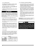
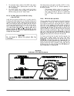
FIGURE 7
Blocked Vent Shut-Off device wiring
Installation: Downflow
DNS-1043 Rev. A2
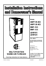
Summary of Contents for AMP105-IE2
Page 20: ...FIGURE 12 1 Diagramme lectrique AMP LBM BMF 075 090 et 105 br leur Beckett 21...
Page 21: ...FIGURE 12 2 Diagramme lectrique AMP LBM BMF 120 140 et 155 br leur Beckett 22...
Page 22: ...FIGURE 12 3 Diagramme lectrique AMP LBM BMF 075 090 et 105 br leur Riello 23...
Page 23: ...FIGURE 12 4 Diagramme lectrique AMP LBM BMF 120 140 et 155 br leur Riello 24...
Page 26: ...FIGURE 12 7 Diagramme lectrique AMP LBM BMF 075 090 et 105 br leur B SCS 27...
Page 27: ...FIGURE 12 8 Diagramme lectrique AMP LBM BMF 120 140 et 155 br leur B SCS 28...
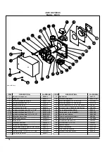
Page 28: ...29 COMPOSANTES ET PI CES DE REMPLACEMENT...
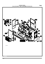
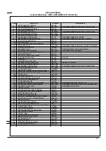
Page 29: ...LISTE DE PI CES Code de fabrication AMP LBM BMF 075 090 105 30 B50058A...
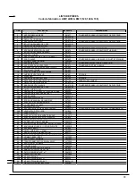
Page 31: ...LISTE DE PI CES Code de fabrication AMP LBM BMF 120 140 155 32 50062A...
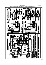
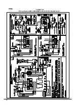
Page 51: ...19 FIGURE 12 1 Wiring diagram AMP LBM BMF 075 090 105 Beckett burner...
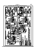
Page 52: ...20 FIGURE 12 2 Wiring diagram AMP LBM BMF 120 140 155 Beckett burner...
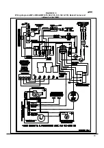
Page 53: ...21 FIGURE 12 3 Wiring diagram AMP LBM BMF 075 090 105 Riello burner...
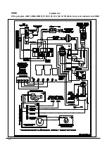
Page 54: ...22 FIGURE 12 4 Wiring diagram AMP LBM BMF 120 140 155 Riello burner...
Page 57: ...FIGURE 12 7 Wiring diagram AMP LBM BMF 075 090 105 B SCS burner 25...
Page 58: ...FIGURE 12 8 Wiring diagram AMP LBM BMF 120 140 155 B SCS burner 26...
Page 59: ...27 COMPONENTS AND REPLACEMENT PARTS...
Page 60: ...PARTS LIST Model AMP LBM BMF 075 090 105 28 B50058A...
Page 62: ...PARTS LIST Model AMP LBM BMF 120 140 155 30 B50062A...


