


Table 5-10: Low byte of D/A channel-1
(Write): wBase+0xc4
Bit 7
Bit 6
Bit 5
Bit 4
Bit 3
Bit 2
Bit 1
Bit 0
D7 D6 D5 D4 D3 D2 D1 D0
Table 5-11: high byte of D/A channel-2
(Write): wBase+0xc8
Bit 7
Bit 6
Bit 5
Bit 4
Bit 3
Bit 2
Bit 1
Bit 0
0 0 0 0 D11
D10
D9
D8
Table 5-12: Low byte of D/A channel-2
(Write): wBase+0xcc
Bit 7
Bit 6
Bit 5
Bit 4
Bit 3
Bit 2
Bit 1
Bit 0
D7 D6 D5 D4 D3 D2 D1 D0
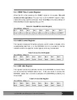
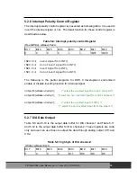
5.2.8 Jumper Status Register
This register shows the status of Hardware jumper setting. About the detail
information, please refer to the following description.
Table 5-13: Jumper status register
(Read): wBase+0xe0
Bit 7
Bit 6
Bit 5
Bit 4
Bit 3
Bit 2
Bit 1
Bit 0
X x
JP9 JP8 JP7 JP5 JP4 JP3
JP3=0
Æ
JP3 is set at 0-20 mA for the current output of channel 1.
JP3=1
Æ
JP3 is set at 4-20 mA for the current output of channel 1
JP4 =0
Æ
JP4 is set at –10 V for internal refernce voltage source of channel 1.
JP4 =1
Æ
JP4 is set at –5 V for internal refernce voltage source of channel 1.
JP5=0
Æ
JP5 is set at Bipolar for channel 1
JP5=1
Æ
JP5 is set at Unipolar for channel 1
JP7=0
Æ
JP7 is set at 0-20 mA for the current output of channel 2
JP7=1
Æ
JP7 is set at 4-20 mA for the current output of channel 2
JP8 =0
Æ
JP8 is set at –10 V for internal refernce voltage source of channel 2
JP8 =1
Æ
JP8 is set at –5 V for internal refernce voltage source of channel 2
JP9=0
Æ
JP9 is set at Bipolar for channel 2
JP9=1
Æ
JP9 is set at Unipolar for channel 2
PISO-DA2/DA2U User Manual (Ver.2.7, Mar. 2012, PMH-020-27)
35


