background image

Web Site: htt://www.icpdas.com.tw 

Contact Us (E-mail):[email protected][email protected]  


Copyright @ 2016 by ICP DAS Co., Ltd. All Rights Reserved. 


4.4


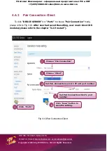
Pair Connection


4.4.1


Pair Connection Server 


To click 

DEVICE SERVER

” >> “

Port1


to choose


Pair Connection


mode,  

please refer to Fig 4-9.

 After user had saved the setting, user must reboot iDS 

modules(please refer to the chapter 

3.2.9 restart

). 


Fig 4-9 Pair Connection Server 


1 

Click  

Port1


2 

Choose 

Pair Connection


Choose 

Server


Set Port Number 

Click 

Save

 button to 

save the setting. 

ГК


Атлант


Инжиниринг

 – 

официальный


представитель


в


РФ


и


СНГ


+7(495)109-02-08 [email protected] www.bbrc.ru 

Summary of Contents for iDS-718i-D

Page 1: ...RoHS DB9 iDS 718iM D CR Intelligent Device Server with 1 RS 232 422 485 Isolated Metal Case RoHS DB9 iDS 728i T CR Intelligent Device Server with 2 RS 232 422 485 Isolated RoHS Terminal block iDS 728...

Page 2: ...information furnished by ICP DAS is believed to be accurate and reliable However no responsibility is assumed by ICP DAS for its use nor for any infringements of patents or other rights of third part...

Page 3: ...N METHOD 21 2 4 1 Factory Setting 21 2 4 2 Setting IP Address 21 3 WEB MANAGEMENT INTERFACE 23 3 1 WEB BROWSER 23 3 2 INITIALIZE SETTING 24 3 2 1 Basic Setting 24 3 2 2 Network Setting 25 3 2 3 SNMP 2...

Page 4: ...4 3 SOCKET MODES 37 4 3 1 TCP Server 37 4 3 2 TCP Client 38 4 3 3 UDP 39 4 4 PAIR CONNECTION 40 4 4 1 Pair Connection Server 40 4 4 2 Pair Connection Client 41 4 5 RFC2217 42 4 6 ETHERNET MODEM 43 1...

Page 5: ...me clock etc These make the iDS 700 becoming one of the most powerful system This device server is designed to add Ethernet and Internet connectivity to any RS 232 and RS 422 485 device and to elimina...

Page 6: ...stributors for more information Save the shipping materials and cartons in case you want to ship in the future 1 2 Features Incorporate Serial Devices in an Ethernet network Virtual COM for 32 bit and...

Page 7: ...Parity None Even Odd Space Mark Stop Bit 1 1 5 2 Flow Control RTS CTS XON XOFF Pull High Low Resistor 1 k for RS 422 485 Non Resistor for RS 232 Software Protocols ICMP IPv4 v6 TCP UDP DHCP BOOTP SSH...

Page 8: ...CPU Module CPU 32 bit RISC 720Mhz RAM 256MB Flash 256MB Peripheral microSD RTC Serial Number Watchdog Buzzer Communication Interface COM1 RS 232 422 485 Isolate 5 Wire COM2 RS 232 422 485 Isolate 5 W...

Page 9: ...NMP MIB II Operation Modes Virtual COM TCP Server TCP Client UDP Pair Connection RFC2217 Terminal Reverse Telnet TCP Modem Modbus Gateway Disabled Authentication Method Local RAIDUS TACACS Power Input...

Page 10: ...Server with 4 RS 232 422 485 Isolated Metal Case RoHS DB9 1 5 Option Accessories GPSU06U 6 CR 24 VDC 0 25 A 6 W Power Supply MDR 20 24 CR 24 VDC 1 A 24 W Power Supply with DIN R DIN KA52F 48 CR 48V 0...

Page 11: ...m tw Contact Us E mail Service icpdas com service icpdas gmail com Copyright 2016 by ICP DAS Co Ltd All Rights Reserved Unit mm 2 Getting Started 2 1 Dimensions and Mounting iDS Series 7 495 109 02 08...

Page 12: ...b Site htt www icpdas com tw Contact Us E mail Service icpdas com service icpdas gmail com Copyright 2016 by ICP DAS Co Ltd All Rights Reserved Unit mm Fig 2 3 7 495 109 02 08 sales bbrc ru www bbrc r...

Page 13: ...Web Site htt www icpdas com tw Contact Us E mail Service icpdas com service icpdas gmail com Copyright 2016 by ICP DAS Co Ltd All Rights Reserved 7 495 109 02 08 sales bbrc ru www bbrc ru...

Page 14: ...ce icpdas com service icpdas gmail com Copyright 2016 by ICP DAS Co Ltd All Rights Reserved DIP Unit mm Fig 2 4 DIP Switch COM 1 4 Mode COM1 M1 M0 DIP Switch RS232 ON OFF RS422 OFF ON RS485 OFF OFF So...

Page 15: ...nt 2 2 1 iDS 718 Series DIP Switch COM1 E1 E1 CON1 1 12 Terminal NO Pin Assignment E1 1 2 3 4 5 6 7 8 9 10 DC 12 48V 11 P PWR 12 P GND CON1 1 12 Pull high low resistors for the RS 422 RS 485 Port DIP...

Page 16: ...OM1 Pin Assignment Pin RS232 RS422 RS485 1 TXD Data 2 RXD TXD Data 3 TXD RXD 4 RXD 5 GND GND GND 6 7 RTS 8 CTS 9 E1 E1 CON1 1 12 Terminal NO Pin Assignment E1 1 2 3 4 5 6 7 8 9 10 DC 12V 48V 11 P PWR...

Page 17: ...ON2 1 18 Terminal NO Pin Assignment COM2 1 RS 422_RxD2 2 RS 422_RxD2 3 RS 422_TxD2 D2 4 RS 422_TxD2 D2 5 RS 232_CTS2 6 RS 232_RTS2 7 RS 232_RxD2 8 RS 232_TxD2 9 GND2 COM1 10 RS 422_RxD1 11 RS 422_RxD1...

Page 18: ...m service icpdas gmail com Copyright 2016 by ICP DAS Co Ltd All Rights Reserved 2 2 3 iDS 448 Series E1 E2 CON1 1 6 Terminal NO Pin Assignment E1 E2 DC 12 48V 1 P PWR 2 P GND 3 P PWR 4 P GND 5 6 E1 E2...

Page 19: ...2016 by ICP DAS Co Ltd All Rights Reserved COM1 4 Pin Assignment Pin RS232 RS422 RS485 1 TXD Data 2 RXD TXD Data 3 TXD RXD 4 RXD 5 GND GND GND 6 7 RTS 8 CTS 9 DIP Switch COM1 4 Mode COM1 M1 M0 DIP Sw...

Page 20: ...m Copyright 2016 by ICP DAS Co Ltd All Rights Reserved 2 3 LED Indicators The iDS 700 contains three LED indicators LED In LED Indicators Color Meaning PWR Red Power is on RUN Green OS is running Ethe...

Page 21: ...sk 255 255 255 0 Gateway 192 168 255 254 Protocol icpdas protocol 2 4 2 Setting IP Address Using web browser IE or Chrome and typing the default IP 192 168 255 1 to connect to the iDS devices to set I...

Page 22: ...s E mail Service icpdas com service icpdas gmail com Copyright 2016 by ICP DAS Co Ltd All Rights Reserved Fig 2 6 Network Set IP Information 2 1 3 COM1 4 Pin Assignm Pin RS232 RS422 R Click Network 7...

Page 23: ...can use the web browser IE 8 or later version Chrome to operate the iDS 700 series web management interface User can input the IP address to connect to the login interface of iDS 700 device Please re...

Page 24: ...2 Initialize Setting 3 2 1 Basic Setting Clicking the Basic Setting to set the iDS s hostname or enable disable the function UDP search the system default don t enable Please refer to the Fig 3 2 Fig...

Page 25: ...l com Copyright 2016 by ICP DAS Co Ltd All Rights Reserved 3 2 2 Network Setting Clicking the Network to set the IP address Please refer to the Fig 3 3 Fig 3 3 Network Set IP Information 2 1 3 Click S...

Page 26: ...das gmail com Copyright 2016 by ICP DAS Co Ltd All Rights Reserved 3 2 3 SNMP Clicking the SNMP to set the SNMP Agent Please refer to the Fig 3 4 Fig 3 4 SNMP 1 Click SNMP Set SNMP Configuration 2 3 C...

Page 27: ...o Ltd All Rights Reserved 3 2 4 Account Password Table Clicking the Account Password Table to set the account information Please refer to the Fig 3 5 Fig 3 5 Account Password Table 1 3 Set account inf...

Page 28: ...Co Ltd All Rights Reserved 3 2 5 Accessible IP Table Clicking the Accessible IP Table to enable disable the rules of IP filter Please refer to the Fig 3 6 Fig 3 6 Accessible IP Table 1 Click Edit 2 En...

Page 29: ...CP DAS Co Ltd All Rights Reserved 3 2 6 Monitor Clicking the Line Async Async Setting to get the COM s information Please refer to the Fig 3 7 Fig 3 8 Fig 3 7 Async Fig 3 8 Async Setting 1 Get COM s i...

Page 30: ...SNMP Trap to set the function of events notification and inform the system administrator Please refer to the Fig 3 9 Fig 3 10 Fig 3 9 Events Fig 3 10 Email SNMP Trap 1 Set the method of notification...

Page 31: ...Rights Reserved 3 2 8 Firmware Upgrade Clicking the Firmware upgrade to update the iDS s firmware Please refer to the Fig 3 11 Fig 3 11 Firmware upgrade 1 2 Please choose the icpdas s firmware packag...

Page 32: ...s gmail com Copyright 2016 by ICP DAS Co Ltd All Rights Reserved 3 2 9 Restart Clicking the Restart to reboot the iDS 700 module Please refer to the Fig 3 12 Fig 3 12 Restart 1 2 Click Restart button...

Page 33: ...Port Basic Setting Clicking the SERIAL PORT SETTING Port1 to set the serial port s basic configuration or click the SERIAL PORT SETTING Advanced Options to set the serial port s modem control and com...

Page 34: ...as com service icpdas gmail com Copyright 2016 by ICP DAS Co Ltd All Rights Reserved Fig 4 2 Port1 s Advanced Option 1 Click Port1 s Advanced Options Set Port s Advanced Options 2 3 Click Save button...

Page 35: ...r vxcomm_driver 4 2 2 Network Setting Please refer to chapter 3 2 2 to set network environment of iDS 700 modules 4 2 3 Configuring Virtual COM Ports Please refer to below steps to set and use the vir...

Page 36: ...ick on iDS 700 s name and check the virtual COM port mappings on the PC please refer to Fig 4 4 Fig 4 4 4 Click Tools Restart Driver and then click the Restart Driver button please refer to Fig 4 5 Fi...

Page 37: ...4 3 1 TCP Server To click DEVICE SERVER Port1 to choose TCP Server mode please refer to Fig 4 6 After user had saved the setting user must reboot iDS modules please refer to the chapter 3 2 9 restart...

Page 38: ...ort1 to choose TCP Client mode please refer to Fig 4 7 After user had saved the setting user must reboot iDS modules please refer to the chapter 3 2 9 restart Fig 4 7 TCP Client Mode 1 Click Port1 2 C...

Page 39: ...SERVER Port1 to choose UDP mode please refer to Fig 4 8 After user had saved the setting user must reboot iDS modules please refer to the chapter 3 2 9 restart Fig 4 8 UDP Mode 1 Click Port1 2 Choose...

Page 40: ...ion Server To click DEVICE SERVER Port1 to choose Pair Connection mode please refer to Fig 4 9 After user had saved the setting user must reboot iDS modules please refer to the chapter 3 2 9 restart F...

Page 41: ...Pair Connection mode please refer to Fig 4 10 After user had saved the setting user must reboot iDS modules please refer to the chapter 3 2 9 restart Fig 4 10 Pair Connection Client 1 Click Port1 6 C...

Page 42: ...ed 4 5 RFC2217 To click DEVICE SERVER Port1 to choose RFC 2217 mode please refer to Fig 4 10 After user had saved the setting user must reboot iDS modules please refer to the chapter 3 2 9 restart Fig...

Page 43: ...SERVER Port1 to choose Ethernet Modem mode please refer to Fig 4 11 After user had saved the setting user must reboot iDS modules please refer to the chapter 3 2 9 restart Fig 4 11 Ethernet Modem 1 Cl...

Reviews: