I-7242D user manual
I-7242D DeviceNet/Modbus RTU Gateway User’s Manual, July 2006, Version 1.1 10/124
2 Hardware Specification
2.1 Hardware Structure
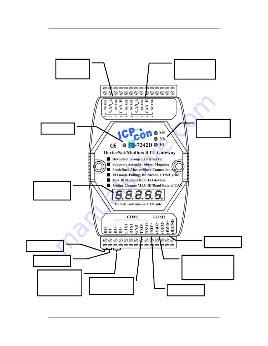
Figure 2-1 Hardware Structure of the I-7242D
CAN Bus
Connector
Bypass CAN
Bus Connector
Power LED
DeviceNet
Status LED
7-segment
LED displays
RS-232 Port
(connect to PC)
RS-485 Port
(Connect to Modbus
devices)
RS-485 Port
(Reserved for
future use)
Power Input
INIT * pin
Alarm Output
Clear Alarm


