background image

5

Icotera A/S, Vibeholms Allé 16, 2605 Brøndby, Denmark - [email protected]

Document version: 1.0

User Guide for 1.17.3 Firmware

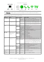
Please note that for some configurations the 5 GHz WiFi interface may be unavailable for up 

to 10 minutes due to prolonged radar detection mechanism, which is signalled by the WiFi 

LED blinking. If the 2.4GHz WiFi is enabled, it will operate normally.

Connectors

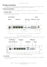
The i68xx front panel includes all the local user connectors that are four RJ-45 10Base-T/100Base-TX/1000Base-T 

ports, two USB ports, two POTS phone ports and one F-type CATV RF output port. Optical fiber connectors are 

placed inside the device. The rest of the fibers (reserve) is covered by a tray which is screwed down to the device 

coaster. It is necessary to take the device cover off in order to access the fibers.

The i4850 bottom panel includes five RJ-45 10Base-T/100Base-TX/1000Base-T ports (1xWAN and 4xLAN), two 

USB ports, and two POTS phone ports.

100Base-BX/1000Base-BX Optical Port

The i68xx uses standard SC port connectors to attach 9/125 micron single mode fiber optic cables. For data it is 

an SC/PC connector with a TX wavelength of 1310 nm and an RX wavelength of 1550 nm, and for CATV it is an SC/

APC connector with a wavelength ranging from 1290 to 1600 nm.

10Base-T/100Base-TX/1000Base-T Ports

The Icotera CPEs use 10Base-T/100Base-TX/1000Base-T RJ-45 (8-pin modular) port connectors. The 10Base-

T/100Base-TX/1000Base-T port connectors are configured as MDI–X (Medium Dependent Interface – Crossover). 

The CPE uses auto sense ports that are designed to operate at 10 Mb/s, 100 Mb/s, or at 1000 Mb/s, depending on 

the connecting device. These ports support the IEEE 802.3u auto negotiation standard, which means that when a 

port is connected to another device that also supports the IEEE 802.3u standard, then the two devices negotiate 

the best speed and duplex mode. The 10Base-T/100Base-TX/1000Base-T RJ-45 switch ports also support half- and 

full-duplex mode operation and can connect to 10 Mb/s, 100 Mb/s or 1000 Mb/s Ethernet segments or nodes.

USB Ports

The Icotera CPE is equipped with one USB 3.0 and one USB 2.0 port that supply 5 V at 500 mA.

POTS Ports

The Icotera CPE uses FXS RJ-11 (2-pin modular) port connectors for POTS (VoIP) connections. The CPE has two 

FXS ports, so it is possible to configure two independent telephone numbers.

Power Port

The power port accepts DC 12V power source. It is important to make sure that the proper power adapter is suitable 

to a particular region.

On/Off Switch

The On/Off switch enables you to switch the CPE on or off, as well as reboot it and restore the last saved configuration.

Reset Button

The Reset button has four modes of operation:
• 

when CPE is operating - 

pressed for less than 10 seconds:

 restarts CPE - WAN LED blinks green.

• 

when CPE is operating - 

pressed for more than 10 seconds:

 restores default CPE settings - WAN and VoIP 1 

LEDs blink green.

• 

when CPE is off - 

power-on with reset button pressed for less than 10 seconds:

 restores default CPE settings 

- WAN LED blinks green.

• 

when CPE is off - 

power-on with reset button pressed for more than 10 seconds:

 boots CPE from the second 

bank - WAN and VoIP 1 LEDs blink green.

Serial Number

The serial number of the Icotera CPE consists of 13 digits. The format of the serial number is PPPPCCXXXXXXX, 

where PPPP is the product ID, CC is the product variant, and XXXXXXX is the running serial number. For example 

6855001234567 would be a serial number of the i6855-00 device with a running number of 1234567

Summary of Contents for i46 Series

Page 1: ...otera A S Vibeholms All 16 2605 Br ndby Denmark info icotera com Document version 1 0 User Guide for Icotera i46xx i68xx and i485x series Published June 2021 Firmware version 1 17 3 Document version 1...

Page 2: ...ibeholms All 16 2605 Br ndby Denmark info icotera com Document version 1 0 User Guide for 1 17 3 Firmware Change log Date Version Reason for a change Author 10 06 2021 1 0 First official release suppo...

Page 3: ...l components of the CPEs i e connectors LEDs and buttons Connector Panel The Icotera i68xx connector panel shown in the following figure contains the power port on off switch reset button connectors a...

Page 4: ...established Red Blinking slow Management interface lease fail Solid No signal 1 2 VoIP registration status Hook status N A Off Line disabled Green Blinking fast Call in progress Blinking slow Off hoo...

Page 5: ...support the IEEE 802 3u auto negotiation standard which means that when a port is connected to another device that also supports the IEEE 802 3u standard then the two devices negotiate the best speed...

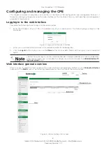
Page 6: ...ser The following login prompt will be displayed Figure 4 Loging into the web interface 2 Enter your username and password in the respective fields of the dialog box 3 Click the Log in button to log i...

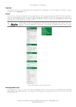
Page 7: ...e the secondary level presents a submenu of available options for a given category By default all menu options are expanded but they can be collapsed by clicking chosen main menu entries Please keep i...

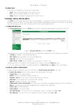
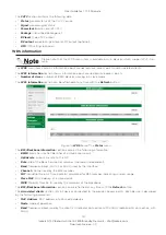
Page 8: ...e MAC address physical address of the connected device Hostname name of the connected device DHCP Static or DHCP if the IP address was assigned by a DHCP server The data presented in the table can be...

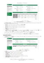
Page 9: ...Mbps FD100 Full Duplex at 100Mbps FD10 Full Duplex at 10Mbps HD100 Half Duplex at 100Mbps HD10 Half Duplex at 10Mbps The data under information menu can be refreshed at any time by clicking the Refres...

Page 10: ...refreshed at any time with the Refresh button As this menu does not include any configurable options the Reset Save and Apply buttons are disabled LAN information The LAN item of the Status main menu...

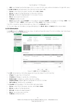
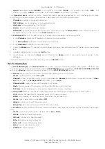
Page 11: ...at any with the Refresh button Wi Fi information The Wi Fi 802 11b g n and Wi Fi 802 11ac menu items contain information about CPE wireless interfaces and their access points Their layout is similar...

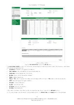
Page 12: ...ess of the connected device Hostname connected device s hostname Expires lease time of the device s address Mode mode of operation Sleep if Yes client is present but does not exchange traffic with hos...

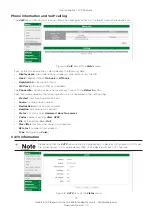
Page 13: ...ress The Phone info section can be refreshed at any time with the Refresh button Each call is described by the following data which is recorded in the VoIP call log Started start time and date of a ca...

Page 14: ...at any time with the Refresh button Figure 14 WDS item of the Status menu The BSS Backbone information section contains the following information BSSID Basic Service Set Identifier of a slave access p...

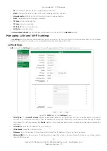
Page 15: ...meters of the cabled and Wi Fi network It also allows to upload and download configuration files LAN settings LAN item of the Settings menu allows to modify parameters of the Local Area Network Figure...

Page 16: ...ent by the router periodically and in response to Neighbor Solicitation packets Reset resets all changes made during the current session Save saves all changes made during the current session Apply ap...

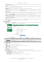
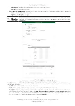
Page 17: ...in the 802 11ac section take precedence Figure 17 Access point settings of the Wi Fi item of the Settings menu The APs sections common for both 802 11b g n and 802 11ac interfaces provide the followin...

Page 18: ...ck the checkbox and enter desired client limit The maximum value is 32 clients Access list behavior defines desired behaviour of the access list allow allows only devices in the access list to connect...

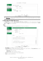
Page 19: ...ms and to reboot the CPE As this menu does not include any configurable options the Reset Save and Apply buttons are disabled Ping Ping diagnostic tool is used for testing reachability of a host in an...

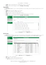
Page 20: ...entered host Stop interrupts running of the traceroute operation Results output of the traceroute operation is displayed continuously in this field Status current state of diagnostic tool as Running...

Page 21: ...ebooting of the CPE has to be confirmed by the user Figure 23 Request for reboot confirmation Figure 24 Request for reset confirmation As this menu does not include any configurable options the Reset...

Page 22: ...anaging remote access The Remote Access item of the Administration menu allows to configure access to the router from a WAN interface Figure 27 Remote Access item of the Administration menu HTTPS sett...

Page 23: ...bles loopback feature for a given port The NAT loopback also known as NAT hair pinning is a feature which permits access to service via the WAN IP address often public IP address from inside the local...

Page 24: ...ions are available under the ALG item of the Services menu Click appropriate checkbox to activate or deactivate any of the following protocols ALG SIP ALG RTSP ALG FTP ALG PPTP ALG L2TP ALG IPSEC Figu...

Page 25: ...for domain name Suffix matching only suffix will be matched Exact matching exact domain name will be matched Wake On LAN The Wake On LAN feature allows to send magic packet to a chosen device Figure 3...

Page 26: ...ice URL Show help displays information about special sequences which can be entered in the fields of this section These sequences will be substituted by appropriate configuration data The Dynamic DNS...

Page 27: ...ccur IPv6 firewall The IPv6 firewall item of the Services menu allows to manually specify exceptions to the stateful IPv6 firewall Figure 36 IPv6 item of the Services menu Use firewall exceptions acti...

Page 28: ...e copyright laws is the responsibility of the user Without limiting the rights under copyright no part of this document may be reproduced stored in or introduced into a retrieval system or transmitted...

Reviews: