background image

Installation of Icotera optical CPE and FTU 

Icotera A/S, Kongevejen 400D, 2840 Holte, Denmark - [email protected] 

Document version: 1.0 


Mounting location recommendations


When considering the layout of fibre optics on your premises and the location of the CPE, it is important 
to consider a number of factors: 


Unobstructed access to the device for maintenance and possible modifications. 

The  device  should  be  mounted  in  such  a  way  as  to  allow  customer  equipment  cables  to  be 
connected  freely,  without  becoming  bent  or  tangled.  Tension  in  the  cables  may  cause  damage  to 
CPE  ports  and  disrupt  connections.  Removing  the  CPE  from  the  FTU  after  it  is  installed  will  also 
require leaving space above the device, due to the nature of the sliding mounting mechanism. 


Free airflow ensuring proper working conditions for the CPE. 

The Icotera's CPE has ample ventilation openings on the sides and top of the CPE. It is important to 
remember  however,  that  free  airflow  must  be  maintained  in  the  area  surrounding  the  device  at  all 
times.  There  should  be  an  unobstructed  space  of  minimum  15  centimetres  around  the  CPE.  The 
projected  temperatures  at  the  premises  must  be  taken  into  consideration  as  well,  as  inadequate 
ambient temperature may lead to environmentally caused failures. 

Environmental conditions should not exceed the following specification: 


Operating temperature: 0 

– 45°C 


Storage temperature: -20 

– 85°C 


Humidity for storage and operation: 5% 

– 95% (non-condensing) 


Optimal WiFi signal coverage across the premises. 

In order to maximise the coverage of wireless networks on the premises, it is important to consider 
mounting the CPE in a way that allows its antennas to propagate the radio signal freely. In case of 
internally mounted antennas, the strongest signal occurs in front of the device and above it. 

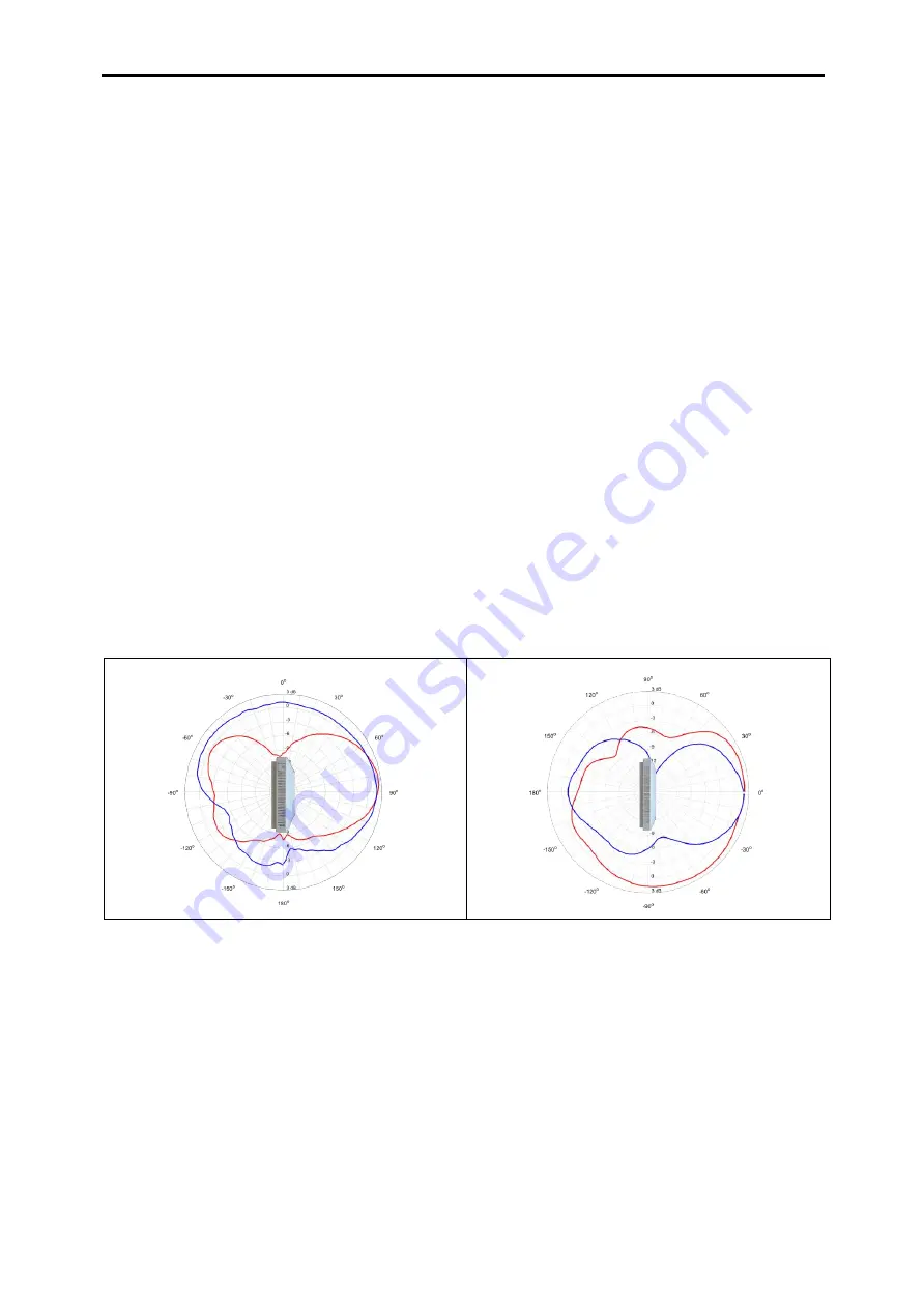
The following charts show a 2.4GHz WiFi propagation of 2 combined antenna units, with side view on 
the left and top view on the right. 


Figure 3. 2.4GHz WiFi propagation 


Summary of Contents for 86071

Page 1: ...olte Denmark info icotera com Document version 1 0 Installation of Icotera optical CPEs and FTUs Installation Guide for Icotera Fibre Termination Units and optical Customer Premises Equipment Publishe...

Page 2: ...tical CPE and FTU 2 Icotera A S Kongevejen 400D 2840 Holte Denmark info icotera com Document version 1 0 Change log Date Version Reason for a change Author 15 03 2017 1 0 First release available to pu...

Page 3: ...be accommodated inside the FTU base up to 2 meters depending on the fibre diameter 10 locations for fibre insertion points Possibility to use SC APC adapters Integrated SCA caps no risk of losing sepa...

Page 4: ...ere humidity heat or cold during storage and transport When moving CPE from cold to warm environments allow it to warm up before powering up as to prevent condensation of moisture inside the device an...

Page 5: ...in its optical variant utilizes laser and fibre optic technology Although the strength of the light beam transmitted through the fibre is comparably low caution should be maintained when handling fibr...

Page 6: ...owing table are not delivered in the CPE package but may be required to install the CPE depending on the installation scenario Item name Amount pcs Item description Splice protector 1 or 2 The number...

Page 7: ...5 Used together with the screw to mount the FTU on the wall M3 5x34 screw 3 5 Used together with the wall plug to mount the FTU on the wall Gas block connector type 1 optional 1 Used for gas sealing w...

Page 8: ...nd top of the CPE It is important to remember however that free airflow must be maintained in the area surrounding the device at all times There should be an unobstructed space of minimum 15 centimetr...

Page 9: ...er follow the steps given below 1 Hold the FTU with your hands Press FTU cover surface with both thumbs as shown below Be careful not to block FTU base with your fingers The FTU cover should slightly...

Page 10: ...re It means that it shouldn t be mounted directly in the corner of the room and it shouldn t be covered by furniture nor any other equipment In order to enable convenient insertion of the fibre cable...

Page 11: ...by knife or any other type of knife that is suitable for the task Try to make the opening as clean and even as possible do not leave jagged edges as these may obstruct straight insertion of the SC APC...

Page 12: ...rill the cavities and mount the wall plugs inside them The FTU base drilling template from Appendix A can be used to mark drilling points before the procedure Figure 13 Wall plugs prepared for mountin...

Page 13: ...oil the fibres around the fixtures at least once in a figure of eight or elliptical pattern but remember not to coil them tightly Note that each subsequent run around the fixture needs approximately 3...

Page 14: ...ch the FTU cover to the FTU base Figure 18 The complete FTU To accommodate a long fibre up to 2 meters with a diameter of 3 mm in the FTU base follow the steps below 1 Make an S shaped coil around two...

Page 15: ...2840 Holte Denmark info icotera com Document version 1 0 Figure 20 Run the fibre between the short and long fences 3 Repeat second step twice to get three full fibre coils between the short and long f...

Page 16: ...era com Document version 1 0 4 Run the fibre between the long fence and the top side of the FTU Figure 22 Run fibre above the long fence 5 Once more run the fibre as in the step 4 and secure fibre plu...

Page 17: ...slide into corresponding notches in the FTU and secure the CPE by sliding it downwards Make sure that the CPE and connectors are fully engaged in the notches a click should be heard Check if the cove...

Page 18: ...ble into the input located on the left side of the interface panel and turn the CPE on with the on off switch located to the right of the DC12V input The LEDs on the front panel should light up progre...

Page 19: ...ease tabs that hook on the CPE and secure it in place Slide CPE upwards Figure 27 The CPE release tabs To open FTU mounted on the wall follow the steps below 1 Hold FTU with your left hand by its top...

Page 20: ...m Document version 1 0 Figure 29 Left side of the FTU over disengaged from the base 5 Hold do not press left side of the FTU cover and pull its right side with your other hand Figure 30 Hold left side...

Page 21: ...ector Figure 32 The gateway FTU base with the blowing air pipe and gas block connector type 1 installed note the 86018 model of the FTU Figure 33 The gateway FTU base with the blowing air pipe and gas...

Page 22: ...Example 3 Blind bottom CPE wall mounted installation When fitted with the gateway blind bottom the CPE can be hung on two wall plug hooks The connection in this configuration is provided with patch c...

Page 23: ...n 1 0 Figure 36 CPE with patch cords connected to the data and CATV ports Example 4 GPON installation GPON installation with a single fibre that enters FTU through a blowing air pipe terminated with a...

Page 24: ...tera optical CPE and FTU 24 Icotera A S Kongevejen 400D 2840 Holte Denmark info icotera com Document version 1 0 Figure 38 FTU base and GPON configuration with gas block type 2 installed note the 8601...

Page 25: ...sed as a template to mark drilling points before mounting the FTU base on a wall The distances between openings for screws are the same for both 86018 and 86071 FTU bases so this template may be used...

Reviews: