background image

4

2

PANEL DESCRIPTION


Software keys

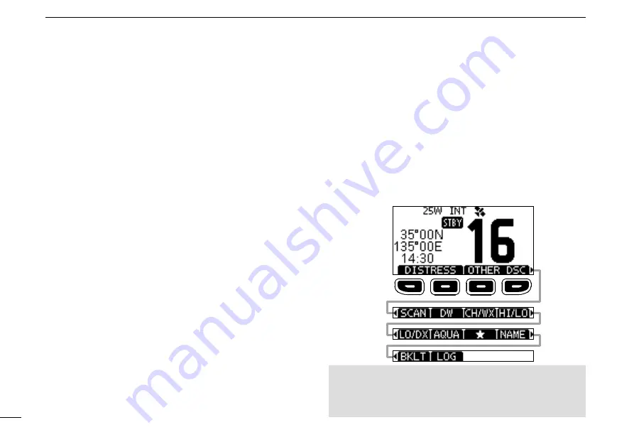
Various often-used functions are assigned to the software 

keys for easy access. The functions’ icons are displayed 

above the software keys, as shown below. 


D

Using the software keys

Selecting a software key function

Push[◄]or[►]toslidethroughtheselectablefunctions

that are assigned to the software keys.

 Push the software key under the function’s icon to select the 

function. 

13 

SOFTWARE KEYS FUNCTION DISPLAY

 (p. 4 ~ 5)

  The functions of each keys are displayed.

   See “Software keys” on the next page for details.

14 

POSITION/TIME READOUTS 

   Readouts the current position and time when valid GPS 

data is received, or when manually entered.


Received GPS data:

 •“NO POS NO TIME” is displayed if no GPS data has been 

received, and then a warning message is displayed for 2 

minutes after turning ON the transceiver.

 •“??”


blinks if no GPS data is received for 30 seconds after 

receiving valid GPS data, and then “??” and a warning 

message are displayed after 10 minutes.

 •A warning message is displayed if no GPS data is received for 4 

hours after receiving valid GPS data.


Manually entered GPS data:

 •A manually entered GPS data is valid for 23.5 hours, and then a 

warning message is displayed.

15 

SCAN INDICATOR

 •“SCAN” or “SCAN 16” is displayed while scanning. (p. 16)

 •“DW” or “TW” and the watched channel number is 

displayed while using the Dualwatch or Tri-watch 

function. (p. 17)

Push [

]

Push [

]

NOTE:

 The displayed icons or their order may differ, 

depending on the transceiver version or the presetting.

When the MMSI code is not set, the software keys for DSC 

function are not displayed.

Summary of Contents for M-330GE

Page 1: ...VHF MARINE TRANSCEIVERS M330 M330E M330G M330GE INSTRUCTION MANUAL INSTRUCTION MANUAL...

Page 2: ...ot responsible for the destruction damage to or performance of any Icom or non Icom equipment if the malfunction is because of Force majeure including but not limited to fires earthquakes storms flood...

Page 3: ...tress and assistance required 6 Give any other information which might facilitate the rescue Or transmit your Distress call using Digital Selective Calling DSC on Channel 70 USING DIGITAL SELECTIVE CA...

Page 4: ...transmit with radio and antenna when persons are within the MPE radius of the antenna unless such persons such as driver or radio operator are shielded from antenna field by a grounded metallic barri...

Page 5: ...de l antenne lorsque des personnes se trouvent l int rieur du rayon d exposition maximale admissible de cette antenne moins que ces personnes comme le conducteur ou l op rateur radio ne soient prot g...

Page 6: ...your authority to operate this transceiver under FCC regulations INFORMATION FCC Cet quipement a t test et reconnu conforme aux limites fix es pour un appareil num rique de classe A conform ment au po...

Page 7: ...o comply with FCC regulations this sticker must be affixed in such a location as to be readily seen from the operating controls of the radio as in the diagram below Make sure the chosen location is cl...

Page 8: ...or where it could cause bodily injury CAUTION DO NOT install the transceiver and or microphone less than 1 meter from the vessel s magnetic navigation compass CAUTION DO NOT place or leave the transce...

Page 9: ...la VHF et le microphone au moins 1 m du compas de route du navire NE PAS utiliser ou placer l metteur r cepteur dans des zones o la temperature est inf rieure 20 ou sup rieure 60 ou dans des zones sou...

Page 10: ...advice INSTALLATION NOTE Installation The installation of this equipment should be made in such a manner as to respect the EC recommended electromagnetic field exposure limits 1999 519 EC The maximum...

Page 11: ...push or Enter Push ENT ENT or DIAL Go to the next tree level Push ENT ENT DIAL or Go back to the previous tree level Push CLR BACK or Cancel Push CLR Exit Push MENU or EXIT IMPORTANT i FEATURES i EXP...

Page 12: ...7 Operation 17 7 DSC OPERATION 18 DSC address ID 18 Entering the position and time 20 Sending DSC calls Distress 21 Sending DSC calls other 24 Receiving DSC calls Distress 32 Receiving DSC calls other...

Page 13: ...cy for a Ship Radiotelephone license application This government issued license states the call sign which is your craft s identification for radio purposes 2 OPERATOR S LICENSE A Restricted Radiotele...

Page 14: ...o display or close the Menu screen 7 POWER VOLUME SQUELCH SWITCH PWR VOL SQL Also described as DIAL in this manual z z Hold down for 1 second to turn the transceiver ON or OFF z z Rotate or push once...

Page 15: ...rns to the Standby mode if no operation occurs during the preset period of time 5 GPS ICON Displayed when valid GPS position data is received Blinks while no position data is received 6 MAIL ICON p 38...

Page 16: ...O POS NO TIME is displayed if no GPS data has been received and then a warning message is displayed for 2 minutes after turning ON the transceiver blinks if no GPS data is received for 30 seconds afte...

Page 17: ...adjust the brightness of the display and keys backlight to between 1 and 7 or OFF LOG LOG p 38 Push to display the received call log or distress message log D D Software key functions Distress Call DI...

Page 18: ...irection or manually resume a scan p 51 e TRANSMIT POWER KEY HI LO z z Push to set the power level to high or low L L Some channels are set to only low power z z While holding down this key turn ON th...

Page 19: ...operating screen This initial code entry can be done only once After entering it can be changed only by your dealer or distributor If your MMSI code has already been entered doing the steps below is n...

Page 20: ...played 2 Push or or rotate DIAL to select ATIS ID Input then push ENT to start entering The ATIS ID Input screen is displayed 3 Enter your ATIS ID 4 Repeat step 3 to enter all 10 digits 5 Push FIN to...

Page 21: ...urn to the previously selected channel push or to display CHAN or CH WX then push the software key below CHAN or CH WX D D Call channel Each Channel Group has separate leisure use Call channels The Ca...

Page 22: ...een is displayed 4 Push or rotate DIAL to select a Channel Group and then push ENT L L Push EXIT to exit the Menu screen L L The selected Channel Group s icon is displayed on the operating screen D D...

Page 23: ...nel icon Adjusting the volume level z z Rotate DIAL to adjust the audio volume level L L If no key is pushed for 5 seconds the screen automatically closes Adjusting the squelch level Squelch enables t...

Page 24: ...screen MENU Radio Settings Call Channel 2 Push or rotate DIAL to select the channel 3 Push ENT to set the selected channel as the Call channel L L Push EXIT to exit the Menu screen Adjusting the back...

Page 25: ...nd transmitting CAUTION DO NOT transmit without an antenna 1 Push or to select the channel to call on The channel number and name are briefly displayed Only when CH Close up is ON L L You cannot trans...

Page 26: ...o scroll Push ENT to enter the selected character Select or or rotate DIAL to move the cursor Push EXIT to cancel editing 5 Push FIN to save the edited name and return to the operating screen AquaQuak...

Page 27: ...through all Favorite channels while also monitoring Channel 16 When a signal is received On Channel 16 The scan pauses until the signal disappears On a channel other than Channel 16 The scan becomes...

Page 28: ...4 To stop the scan push SCAN Setting Favorite channels You can quickly recall often used channels by setting them as Favorite channels You can set Favorite channels in each Channel Group 1 Select a C...

Page 29: ...all channel while receiving on another channel Dualwatch Tri watch Operation 1 Select Dualwatch or Tri watch on the Menu screen 2 Push or to select a channel 3 Push or to display DW Dualwatch or TW Tr...

Page 30: ...a number using and Push ENT to set the selected number Select or or rotate DIAL to move the cursor NOTE The first digit is fixed as 0 for a Group ID The first two digits are fixed as 0 for any coast s...

Page 31: ...e 4 After entering push FIN to save and return to the previous screen The entered name is displayed NOTE The first digit is fixed as 0 for a Group ID The first two digits are fixed as 0 for any coast...

Page 32: ...id only for 23 5 hours or until turning OFF the transceiver 1 Display the POSITION INPUT screen MENU DSC Settings Position Input 2 Enter the latitude TIP Select a number or a compass direction using S...

Page 33: ...ong beep sound The backlight blinks 3 After sending wait for an Acknowledgement call Waiting for ACK is displayed The Distress call is automatically sent every 3 5 to 4 5 minutes until an Acknowledgem...

Page 34: ...Entering the position and time on page 20 for details 4 While lifting up the key cover hold down DISTRESS the red button for 3 seconds until you hear 3 short countdown beeps and a long beep sound The...

Page 35: ...wording of the cancellation by pushing 4 After communicating push FINISH The screen to the right is displayed 5 Push STBY to finish the Distress Cancel call Returns to the operating screen D D Distre...

Page 36: ...l Call is displayed and then Waiting for ACK is displayed L L If Channel 70 is busy the transceiver stands by until the channel becomes clear 9 When you receive an Acknowledgement Able to comply An al...

Page 37: ...eived an Individual call p 33 send an Acknowledgement to the calling station When you send an Acknowledgement select Able to Comply Propose New CH or Unable to Comply 1 While an Individual call is bei...

Page 38: ...ment type ABLE Able to Comply Sends an Acknowledgement call without any changes UNABLE Unable to Comply Sends an Acknowledgement call but cannot communicate NEW CH Propose New CH Able to communicate b...

Page 39: ...displayed 3 Select All Ships and then push ENT The All Ships call is selected and returns to the OTHER DSC screen 4 Select Category and then push ENT The CATEGORY screen is displayed 5 Select a categ...

Page 40: ...and then push ENT The Group call is selected and returns to the OTHER DSC screen 4 Select Address and then push ENT The ADDRESS screen is displayed 5 Select the group to send a Group call to and the...

Page 41: ...u screen 2 Select Test and then push ENT The Test call is selected and returns to the OTHER DSC screen 3 Select Address and then push ENT The ADDRESS screen is displayed 4 Select a station to send the...

Page 42: ...You can send a Position Request call or Polling request call to a station depending on the presetting Example Sending a Position Request call 5 Push STBY A confirmation screen is displayed 6 Push OK t...

Page 43: ...you can manually enter the position and time in Position item on this screen See Entering the position and time on page 20 for details 4 Push CALL to send the Position Reply call 6 Push CALL to send t...

Page 44: ...CH Auto SW item is set to Manual p 42 Pauses the countdown until the assigned channel is automatically selected Select RESUME to resume the countdown The call is saved in the DSC Log ACPT Accept Accep...

Page 45: ...you display the call message ACPT Accept Accepts the call The assigned channel is automatically selected The call is saved in the DSC Log The received call s information is displayed Push the softwar...

Page 46: ...turns to the operating screen The call is saved in the DSC Log blinks continuously until you display the call message PAUSE Pause L L PAUSE is not displayed if the CH Auto SW item is set to Manual p 4...

Page 47: ...yed 1 Push ALARM OFF to turn OFF the alarm L L The traffic channel that is assigned by the caller is automatically selected after 10 seconds by default 2 Push the software key below your next operatio...

Page 48: ...ll is saved in the DSC Log UNABLE Unable to Comply Sends the Acknowledgement Unable to Comply Displays the Acknowledgement information and then returns to the operating screen by pushing EXIT The call...

Page 49: ...SC Log ACPT Accept Accepts the call Displays the received call s information The call is saved in the DSC Log Push ACK and then push CALL to send a Test Acknowledgement call p 30 Push RESEND to resend...

Page 50: ...eceived DSC Log The transceiver saves up to 30 received Distress call messages and 50 received Others call messages in your DSC Log On the operating screen is displayed when there is an unread call me...

Page 51: ...The TX CALL LOG screen is displayed 3 Push or to scroll through the log 4 Push ENT to display the sent call s information EXIT Returns to the operating screen BACK Returns to the previous screen DEL...

Page 52: ...rating screen NOTE The Task mode has a Time out Timer TOT function After a certain period of time has passed without any operation on a task the transceiver automatically exits the Task mode and retur...

Page 53: ...Y Holds the task and returns to the operating screen INFO Displays the task information DEL Finishes the selected task HOLD Holds the selected task ACTIVE Activates the selected task D D Activating th...

Page 54: ...nual Manually sends an Acknowledgement call Polling ACK Default Auto Auto Automatically sends an Acknowledgement call Manual Manually sends an Acknowledgement call Test ACK Default Auto Auto Automatic...

Page 55: ...ved Routine Default On An alarm sounds when a Routine DSC call is received Warning Default On An alarm sounds when No MMSI code is entered The position data has not been received for 2 minutes after t...

Page 56: ...l Push ENT to start the Self Test L L When the sending and receiving DSC signals match OK is displayed Procedure Default Single For only the USA version You can select the type of task for the transce...

Page 57: ...g the transponder 2 Push DSC to display the Voice channel selection screen and then push Y Z to select a Voice channel Voice channels are already preset into the transponder in the recommended order W...

Page 58: ...mply is received push ALARM OFF to turn OFF the alarm and then select the Intership channel specified in step 2 A different Intership channel will be selected if the station you called cannot use the...

Page 59: ...h or rotate DIAL to select Configuration and then push ENT The CONFIGURATION screen is displayed L L Holding down or sequentially scrolls up or down through the Menu screen 3 Push or rotate DIAL to se...

Page 60: ...UTC Offset p 49 Display Contrast p 12 Inactivity Timer p 49 Key Beep p 49 GPS p 50 Key Assignment p 49 DSC Log Item Reference Item Reference Received Call Log p 38 Transmitted Call Log p 39 Radio Set...

Page 61: ...ctions and their order may differ depending on the transceiver version or presetting Set Default Sets the software key function order as default L L The default setting may differ depending on the tra...

Page 62: ...The default setting differs depending on the transceiver version L L See page 15 for details Normal Scan Scans all Favorite channels in the selected channel group Priority Scan Sequentially scans all...

Page 63: ...n alert On with Scan The preset Weather channels are sequentially checked while scanning On The previously selected last used Weather channel is checked while scanning Off The Weather Alert tone is no...

Page 64: ...L This setting may not be usable depending on the transceiver version or presetting CH Close up You can select whether or not to display the channel name when changing the operating channel On The ch...

Page 65: ...pment to receive position data from other ships An NMEA 0183 ver 2 0 or later sentence format DSC or DSE compatible navigation equipment is required The supplied GPS outputs RMC GSA and GSV format sen...

Page 66: ...er to the high density D Sub 15 pin connector of the MA 500TR using the OPC 2014 cable After connecting an Individual DSC call can be made to the AIS target using the transponder without entering the...

Page 67: ...wn the source of the problem repair it and replace the damaged fuse with a new one of the proper rating Fuse rating 10 A Cleaning If the transceiver becomes dusty or dirty wipe it clean with a soft dr...

Page 68: ...than 5 kg using the 2 supplied screws 5 20 mm CAUTION KEEP the transceiver and microphone at least 1 meter 3 3 ft away from the vessel s magnetic navigation compass Mounting Example NOTE When mountin...

Page 69: ...meter away from your vessel s magnetic navigation compass 4 Attach the clamps on both sides of the transceiver L L Make sure that the clamps align parallel to the transceiver body Clamp 5 Tighten the...

Page 70: ...1 6 lb D D Transmitter Output power 25 W or 1 W Modulation system Variable reactance frequency modulation Maximum frequency deviation 5 kHz Spurious emissions IC M330 IC M330G Less than 70 dBc High po...

Page 71: ...s b ais transponder To transmit individual DSC calls to a selected AIS targets D D GPS Antenna Frequency 1575 42 MHz Channel Acquisition tracking Maximum 24ch Calculation Maximum 12ch Deferential sate...

Page 72: ...p 6 Scan does not start More than 2 favorite channels are not set Set the Favorite channels p 16 No beep sounds The Key Beep function is OFF Turn ON the Key Beep function p 47 Individual or Group ID...

Page 73: ...27 27 157 350 161 950 27 157 350 157 350 27A 157 400 157 400 28A 28 28 157 400 162 000 28 28B Rx only 162 000 60 156 025 160 625 60 156 075 160 675 61 61A 156 075 156 075 156 125 160 725 62 62A 156 1...

Page 74: ...325 160 925 76 3 156 825 156 825 86 157 325 161 925 07 156 350 160 950 17 1 156 850 156 850 27 157 350 161 950 67 156 375 156 375 77 156 875 156 875 87 157 375 157 375 1037 4 157 850 157 850 P4 4 161...

Page 75: ...63 13 1 2 3 4 5 6 7 8 9 10 11 14 15 16 12 13 TEMPLATE R8 5 16 Maximum 156 5 6 5 32 53 2 3 32 66 5 2 5 8 Unit mm inch 139 5 15 32...

Page 76: ......

Page 77: ...pose of these products as unsorted municipal waste Dispose of them according to the laws in your area About CE and DOC Hereby Icom Inc declares that the versions of IC M330E IC M330GE which have the C...

Page 78: ...trast Configuration 49 Distress call Cancel call 23 Receiving 32 Regular call 22 Sending 21 Simple call 21 DSC Address ID 18 Log Received 38 Log transmitted 39 Settings 42 DSC data output 43 Dual Tri...

Page 79: ...Radio Info 52 Receiving 13 S Scan Normal 15 Priority 15 Starting 16 Types 15 Scan Timer Radio Settings 50 Scan Type Radio Settings 50 Self test DSC Settings 44 Simple call Distress call 21 Software ke...

Page 80: ...1 1 32 Kamiminami Hirano ku Osaka 547 0003 Japan A7420D 1EX 3 Printed in Japan 2017 2019 Icom Inc Mar 2019...

Reviews: