Icom ID-880H Instruction Manual Download Page 33

18

2

BASIC OPERATION

N

 Selecting output power

The transceiver has 3 output power levels to suit your operat-
ing requirements. Low output powers during short-distance 
communications may reduce the possibility of interference to 
other stations and will reduce current consumption.

±

  Push 

[LOW]

 several times to select the output power.

 *approx.
• The output power can be changed while transmitting.

The microphone can also be used to select output power.

HIGH

4

MID

5

LOW

6

±

  Push [

HIGH

 4(DTCS)] for high output power; 

[

MID

 5(DTCS

S

)] for middle output power; and 

[

LOW

 6(DTMF)] for low output power.

 • 


The output power can be changed via the microphone 
during receive only.

N

 Operating mode selection

Operating modes are determined by the modulation of the 
radio signals. The transceiver has total 5 operating modes 

(FM, FM-N, AM, AM-N and DV* modes)

. The mode selection is 

stored independently for each band and memory channel.

Typically, AM mode is used for the air band 

(118–136.995 MHz)

and receive is only available.
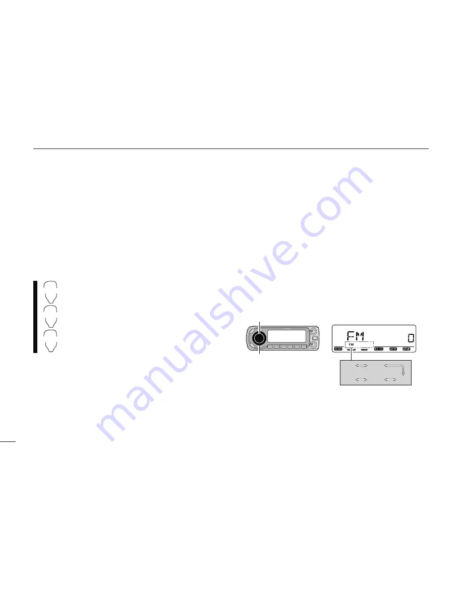
q

  Select the desired frequency band in VFO mode, or the 

desired memory channel.

w

  Push and hold 

[MODE]

(BAND) for 1 sec., then rotate 

[DIAL]

 to select the desired operating mode from FM, 

FMN, AM, NAM and DV.

[DIAL]

[MODE]

Selected operating mode is displayed.

FM

FMN

NAM

AM

DV

Summary of Contents for ID-880H

Page 1: ...ause harmful interference and 2 this device must accept any interference received including interference that may cause undesired operation WARNING MODIFICATION OF THIS DEVICE TO RECEIVE CEL LULAR RADIOTELEPHONE SERVICE SIGNALS IS PROHIBITED UNDER FCC RULES AND FEDERAL LAW INSTRUCTION MANUAL ID 880H VHF UHF DIGITAL TRANSCEIVER ...

Page 2: ...ion operation ready Text message and call sign exchange Transmitting position data with a third party GPS receiver M DR D STAR Repeater mode and repeater list allow you to operate D STAR repeater simply M Switchable VHF and UHF transceiver M 50 W high transmit output power VHF band 50 W for UHF band M Detachable controller for flexible installa tion M Large tuning dial and band switch button IMPORT...

Page 3: ...n electric shock or damage the transceiver NEVER place the transceiver where normal operation of the ve hicle may be hindered or where it could cause bodily injury NEVER let objects impede the operation of the cooling fan on the rear panel DO NOT push the PTT when not actually desiring to transmit DO NOT allow children to play with any radio equipment contain ing a transmitter During mobile operat...

Page 4: ... more of the following measures Reorient or relocate the receiving antenna Increase the separation between the equipment and re ceiver Connect the equipment into an outlet on a circuit different from that to which the receiver is connected Consult the dealer or an experienced radio TV technician for help The following accessories are supplied with the transceiver qDC power cable 3 m 1 wSeparation ...

Page 5: ...PU and memory device could be deleted NEVER put the controller near a clock television set CRT type magnetic compass and any magnetic IC cards credit cards etc It may cause the product to malfunction and the content of the magnetic card could be deleted Please note that the controller may drop off when a high im pact or vibration is applied D Installation methods Single body installation Transceiv...

Page 6: ...Select a location which can support the weight of the trans ceiver and does not interfere with driving We recommend the locations shown in the diagram below NEVER place the transceiver or remote controller where normal operation of the vehicle may be hindered or where it could cause bodily injury NEVER place the transceiver or remote controller where air bag deployment may be obstructed DO NOT pla...

Page 7: ...ws nuts and washers through the mounting bracket and tighten eAdjust the angle for your suitable position Nut Spring washer When using self tapping screws Flat washer Mounting nut Mounting bracket 25 D Microphone connection A microphone connector is available on the main unit front panel Connect the supplied microphone connector as illus trated below Transceiver Microphone III QUICK REFERENCE GUID...

Page 8: ...ease latch D Separation cable connection Using the supplied separation cable 3 4 m 11 2 ft the con troller can be separated from the main unit doubling as a remote controller Connect the controller and the main unit using with the sup plied separation cable as follows Controller Main unit IV QUICK REFERENCE GUIDE 1 2 3 4 5 6 7 8 9 10 11 12 13 14 15 16 17 18 19 ...

Page 9: ...cky tape etc as at left then attach remote controller to the bracket When installing into your vehicle qRemove two screws and magnets from the remote control ler wAttach the supplied remote controller bracket as below Remote controller bracket Remote controller eAttach the remote controller on to the optional MB 65 as below Remote controller bracket Optional MB 120 Adjust the viewing angle for max...

Page 10: ...OURCE ID 880H Fuses 20 A black red _ 12 V Grommet NOTE Use terminals for the cable connections RWARNING NEVER remove the fuse holders Crimp Solder 12 V battery Supplied DC power cable red _ black D DC power supply connection Use a 13 8 V DC power supply with at least 13 A capacity Make sure the ground terminal of the DC power supply is grounded CONNECTING TO A DC POWER SUPPLY DC power supply 13 8 ...

Page 11: ...a To antenna Antenna connector The antenna uses a PL 259 connector PL 259 CONNECTOR 30 mm 10 mm soft solder 10 mm 1 2 mm solder solder Soft solder Coupling ring q Slide the coupling ring down Strip the cable jacket and tin w Strip the cable as shown at left Soft solder the cen ter conductor e Slide the connector body on and solder it r Screw the coupling ring onto the connector body 10 mm 3 8 in N...

Page 12: ...Although you have purchased a brand new transceiver some settings may be changed from the factory defaults because of the Quality Control QC process Resetting the CPU is necessary to start from factory default VFO MHz Partial reset S MW While pushing and holding S MW and VFO MHz keys push and hold for 1 sec to reset the CPU 2 Selecting the operating frequency band The ID 880H can use 2 m or 70 cm ...

Page 13: ... dial in the frequency you want to use Pages 17 and 18 will instruct you on how to set the tuning speed DIAL Rotate DIAL to tune the frequency Using the HM 133 You can directly enter the frequency with the HM 133 keypad EXAMPLE Setting frequency to 145 3625 MHz Push Push Push Push ...

Page 14: ...he USA version has an auto repeater function therefore set ting duplex is not required DUP DIAL 2 Repeater tone Push and hold TONE M CALL for 1 sec then rotate DIAL to select TONE if the repeater requires a subaudible tone to be accessed TONE DIAL Using the HM 133 Plus or minus duplex selection and the repeater tone setting can be made easily via the HM 133 Push DUP 7 TONE for minus duplex DUP 8 T...

Page 15: ...MW for 1 sec to program 3 beeps sound Return to VFO mode automatically after programming Memory channel number automatically increases when continuing to push MW S MW after programming Using the HM 133 qPush MR CALL to select memory mode wPush ENT C T OFF first then enter the desired memory channel via the keypad ePush VFO LOCK to select VFO mode then set the de sired operating frequency including ...

Page 16: ...nects a TNC Terminal Node Controller etc for data communications The receiver can support 1200 9600 bps packet communication AFSK GMSK tEXTERNAL SPEAKER JACK SP Connects an 8 Ω speaker Audio output power is more than 2 0 W Connect an optional cloning cable OPC 478UC or OPC 474 for data cloning yPOWER RECEPTACLE DC13 8V Accepts 13 8 V DC 15 with the supplied DC power cable NOTE DO NOT use a cigaret...

Page 17: ...canning direction p 75 rBAND MODE KEY BAND MODE Push to enter band selection state p 15 Rotating DIAL selects the band Push and hold for 1 sec to enter operating mode selec tion state p 15 Rotating DIAL selects the operating mode tVFO MHz TUNING SCAN KEY VFO MHz SCAN Push to select VFO mode p 17 During VFO mode operation push to select 1 MHz and 10 MHz tuning steps p 75 Push and hold for 1 sec to ...

Page 18: ...e peater call sign R2 link repeater call sign and MY your own call sign Push and hold for 1 sec to set the received call signs stations and repeaters to current call sign p 30 oOUTPUT POWER DUPLEX KEY LOW DUP Each push changes the output power selection p 21 LOW MID and HIGH no indicator visible are available Push and hold for 1 sec to enter duplex operation se lection state p 30 Rotating DIAL sel...

Page 19: ...nning p 75 rOUTPUT POWER INDICATORS LOW appears when low output power MID appears when middle output power no indication appears when high output power is selected tOPERATING MODE INDICATOR p 21 Shows the selected operating mode FM FMN FM narrow AM NAM AM narrow and DV Digital voice are available DVG DV A appears when GPS transmission or GPS A trans mission is selected in DV mode p yBUSY INDICATOR...

Page 20: ...eci fied as a program skip frequency 5WEATHER ALERT INDICATOR p 123 WX appears when the weather alert function is in use Available with the USA version only 6TONE INDICATOR During FM FM N mode operation T appears while the repeater tone is in use p 30 TSQL appears while the tone squelch function is in use p 86 TSQL R appears while the reverse tone squelch function is in use p 87 DTCS appears while ...

Page 21: ...9 During programming state for call signs repeater list memory name etc push to erase the selected char acter During programming state for call signs repeater list memory name etc push and hold for 1 sec to erase all character following the corsor wLEFT KEY CS During programming state for call signs repeater list memory name etc push to move the cursor left During menu screen operation push to sel...

Page 22: ... for 1 sec to start scanning p 75 rACTIVITY INDICATOR Lights red while any key except FUNC and DTMF S is pushed or while transmitting Lights green while the one touch PTT function is in use tKEYPAD pgs 12 13 yFUNCTION INDICATOR Lights orange while FUNC is activated indicates the secondary function of keys can be accessed Lights green when DTMF S is activated DTMF sig nals can be transmitted with t...

Page 23: ... VFO mode enters operating band selec tion In memory mode enters bank selection p 64 Starts and stops tone scanning p 90 Turns the one touch PTT function ON and OFF p 26 Turns the DTCS squelch ON p 86 Turns the DTCS pocket beep function ON p 86 Turns the DTMF memory encoder function ON p 83 Turns the subaudible tone encoder ON p 31 Turns the CTCSS pocket beep function ON p 86 Turns the tone squelc...

Page 24: ...0 Adjusts the squelch level decrement p 20 Stores the set frequency etc into the selected memory channel when pushed and held p 63 Advances the memory channel number when continuously pushed after pro gramming is completed p 63 DTMF memory encoder function OFF p 83 Turns the subaudible tone encoder pocket beep or CTCSS DTCS tone squelch OFF pgs 31 86 Mutes the audio p 27 Mute function is released ...

Page 25: ... and hold to transmit release to receive wUP DOWN KEYS UP DN Push either key to change operating frequency memory channel set mode setting etc pgs 17 61 98 Push and hold either key for 1 sec to start scanning p 75 eUP DN LOCK SWITCH Slide to toggle UP DN keys function ON and OFF ...

Page 26: ...ee p for details BAND DIAL Frequency band initial is displayed qPush BAND and rotate DIAL to select the desired fre quency band Pushing Y Z on the microphone also selects the band wPush BAND to return to frequency indication in the se lected frequency band BAND Y Z z Push BAND to enter frequency band selec tion The frequency band is displayed x Push Y Z to select the desired frequency band c Push ...

Page 27: ...ransmitting and receiving are generated and controlled by the VFO D Memory mode Memory mode is used for operation on memory channels which store programmed frequencies q Push M CALL to select memory mode Push M CALL several times to select Memory Call Weather channels in sequence Weather channels are available for the U S A version only X indicator appears when memory mode is selected Appears M CA...

Page 28: ...cation MR CALL Y Z z Push and hold MR CALL for 1 sec to se lect call channels Whether channels cannot be selected by the HM 133 x Push or to select the desired call channel D DR D STAR Repeater mode DR D STAR Repeater mode is used for the D STAR re peater operation In this mode you can select the pre pro grammed repeaters and UR your call sign easily q Push DR to select DR mode appears when call c...

Page 29: ...low 100kHz disappear While 10 MHz tuning step is selected the digit below 1 MHz disappear wTo change the frequency in 1 MHz 10 MHz for some versions steps push VFO MHz then rotate DIAL Pushing and holding VFO MHz for 1 sec starts scan function If scan starts push VFO MHz again to cancel it N Using the Y Z keys YZ Push Y or Z to select the desired frequency Pushing and holding Y Z for 1 sec activat...

Page 30: ...Setting frequency to 145 3625 MHz N Tuning step selection Tuning steps are the minimum frequency change increments when you rotate DIAL or push Y Z on the microphone Independent tuning steps for the left and right bands as well as each frequency band can be set for individual tuning con venience The following tuning steps are available 5 kHz 6 25 kHz 10 kHz 12 5 kHz 15 kHz 20 kHz 25 kHz 30 kHz 50 ...

Page 31: ...n only VOL and SQL can be used while the channel lock function is in use Also TONE 1 TONE 2 DTMF tones or DTMF memory contents can be trans mitted from the microphone VFO LOCK Push and hold VFO LOCK for 1 sec to turn the lock function ON and OFF D Microphone keypad lock This function locks the microphone keypad 16KEY L Push FUNC then SQLZ D 16KEY L to turn the microphone keypad lock function ON an...

Page 32: ...nd SQLY D MUTE SQLZ 16KEY L respectively VOL for audio or SQL for squelch appears during set Show set level N Transmitting CAUTION Transmitting without an antenna may damage the transceiver NOTE To prevent interference listen on the channel be fore transmitting by pushing MONI or MONI 1 BANK on the microphone qSet the operating frequency pgs 15 17 Select output power if desired See section at righ...

Page 33: ...iddle output power and LOW 6 DTMF for low output power The output power can be changed via the microphone during receive only N Operating mode selection Operating modes are determined by the modulation of the radio signals The transceiver has total 5 operating modes FM FM N AM AM N and DV modes The mode selection is stored independently for each band and memory channel Typically AM mode is used fo...

Page 34: ...ation level can be adjusted up to 10 dB approx between 13 o clock and fully clockwise position Squelch is open Squelch attenuator Squelch threshold Shallow Deep Noise squelch NOTE The squelch attenuator functions even when the monitor function is in use Thus it is recommended to set the SQL control between the 10 and 13 o clock positions when using the monitor function D Squelch attenuator setting...

Page 35: ...ush MONI 1 BANK again to cancel the function NOTE When the SQL adjustment is set too far clock wise 13 17 o clock position the squelch attenuator is activated To monitor weak signals on the operating fre quency deactivate the squelch attenuator function See page 22 for details N Audio mute function This function temporarily mutes the audio without disturbing the volume setting microphone only MUTE...

Reviews: