INSTRUCTION MANUAL
UHF MOBILE TRANSCEIVER
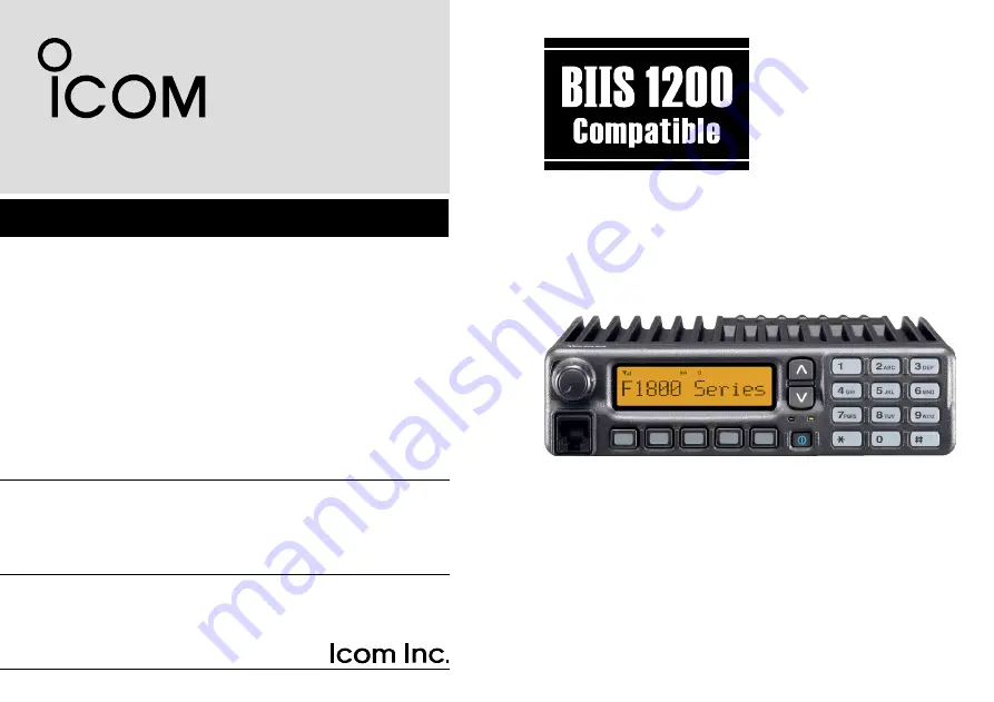
iF2810
iF2710
VHF MOBILE TRANSCEIVER
iF1810
iF1710
Above photo shows the IC-F1810 or IC-F2810.
Page 1: ...INSTRUCTION MANUAL UHF MOBILE TRANSCEIVER iF2810 iF2710 VHF MOBILE TRANSCEIVER iF1810 iF1710 Above photo shows the IC F1810 or IC F2810...
Page 2: ...ator for details concerning your transceivers programming EXPLICIT DEFINITIONS WORD DEFINITION RWARNING Personal injury fire hazard or electric shock may occur CAUTION Equipment damage may occur NOTE...
Page 3: ...age the trans ceiver DO NOT use or place the transceiver in areas with tem peratures below 25 C or above 55 C or in areas subject to direct sunlight such as the dashboard DO NOT operate the transceive...
Page 4: ...a call 14 n Transmitting a call 16 n Receiving a message 18 n Transmitting a status 20 n Transmitting an SDM Short Data Message 21 n Position data transmission 23 n Printer connection 23 n Digital AN...
Page 5: ...Rotate to select an operating channel etc IC F1810 F2810 UP DOWN Keys Push to select an operating channel etc The desired function can be assigned by your dealer p 3 r 10 KEYPAD IC F1810 or IC F2810 o...
Page 6: ...he supplied or optional microphone has a PTT switch and a hanger hook The following functions are available when the microphone is on or off hook Automatic scan start when on hook Automatic priority c...
Page 7: ...following functions can be assigned to DIAL UP DOWN P0 P1 P2 P3 and P4 programmable func tion keys Consult your Icom dealer or system operator for details con cerning your transceivers programming If...
Page 8: ...g CH Up CH Down SCAN B START STOP KEY Push to start and cancel scanning operation In case of transmission during scan pauses scanning Scanning re sumes after a specified time period has passed after t...
Page 9: ...acklight ON for about 5 sec when the backlight function is turned OFF in user set mode LOCK KEY Push and hold to electronically lock all programmable keys except the following Call incl Call A and Cal...
Page 10: ...turn the surveillance function ON or OFF When this function is turned ON the beep is not emitted and the LCD backlight does not light when a signal is received or a key is pushed etc TX CODE ENTER KEY...
Page 11: ...efer to p 13 also OPT 1 2 3 KEYS Push to control the output signal level of the optional ports in the optional unit connector DIGITAL BUTTON KEY BIIS operation only Push to select the call ID list tra...
Page 12: ...P4 e When the PASSWORD indication does not clear after in putting 6 digits the input code number may be incorrect Turn the power off and start over in this case n Channel selection Several types of ch...
Page 13: ...Up or CH Down or rotate CH Up Down to select a channel in sequence e When receiving a call adjust the audio output level to a comfortable listening level Transmitting Wait for the channel to become c...
Page 14: ...as TX Code CH Select assigned to it the indication can be toggled between the operating channel number or name and TX code channel number or name When the TX code channel number or name is displayed C...
Page 15: ...for setting the digit to the right will blink automatically without pushing TX Code CH Select y Repeat r and t to input all allowable digits u Push Call or PTT to transmit the edited TX code IC F1810...
Page 16: ...ate CH Up Down to select the desired DTMF channel e Push DTMF Autodial to transmit the DTMF code in the selected DTMF channel n Scrambler function The voice scrambler function provides private communi...
Page 17: ...e P1 P0 P2 w Push P0 several times to select the appropriate item Then push Up or Down or rotate DIAL to set the de sired level condition Available set mode functions are Backlight LCD Contrast Beep B...
Page 18: ...ion se lects the operating channel After pushing Digital or TX Code CH Select selects call list or TX code channel respectively n Receiving a call Individual call q When an individual call is received...
Page 19: ...gnal r To finish the conversation push P4 Moni Audi to send the Clear down signal Either station can send a Clear down signal CLR DOWN is displayed for 2 sec approx disappears and the transceiver retu...
Page 20: ...ng each call However an error beep sounds and FAILED is displayed when no an swer back is received after the calls r Push PTT to transmit release to receive t Push P4 Moni Audi to send the Clear down...
Page 21: ...setting the digit to the right will blink automatically without pushing P3 TX Code Enter t Repeat e and r to input all allowable digits y Push P0 Call or PTT to call PTT call can be made only when PT...
Page 22: ...en the scroll timer is set to OFF In this case push Status Up Status Down to display the status message manually Receiving an SDM Short Data Message q When an SDM is received Beeps sound The calling s...
Page 23: ...igital momentarily Displays message memory When a message is available M E S SA G E M SG When no message is available M E S SA G E N O M S G e Push Up or Down or rotate DIAL to select the desired mess...
Page 24: ...sent with both individual and group calls Transmitting a status q While in the standby condition push P1 Digital then push Up or Down or rotate DIAL to select the desired station group code w Push P1...
Page 25: ...station group code w Push P1 Digital again then push Up or Down or rotate DIAL to select the desired SDM Or you can select the desired SDM using Status Up Sta tus Down key directly M E S S A G E 1 S...
Page 26: ...ed character r Push to move the cursor to the right push M to move the cursor to the left t Repeat steps e and r to set the desired text message y Push P1 Digital for 1 sec to overwrite the set conten...
Page 27: ...nd the ID of the station who sent the message Ask your dealer or system operator for connection details n Digital ANI The own ID can be transmitted each time the PTT is pushed log in or released log o...
Page 28: ...When one of the following operations is performed the trans ceiver selects the Priority A channel automatically Priority A is selected when Clear down signal is received transmitted Set the Move to P...
Page 29: ...round for microphone on off hook functions See p 2 t OPTIONAL CABLE OPC 617 Connect an external modem unit dimmer control etc y Supplied speaker SP 22 IC F1810 or IC F2810 only IC F1710 and IC F2710 h...
Page 30: ...unting screws M5 12 Self tapping screws M5 16 Nuts IC F1810 F2810 only Function name stickers There are no names on the programmable function keys since the functions can be freely assigned to these k...
Page 31: ...duce the vibration effects Felt Felt Flat washer Spring washer When using self tapping screws n Optional UT 109 or UT 110 installation Install the optional UT 109 or UT 110 unit as follows q Turn the...
Page 32: ...Cut off the bushing as in the illustration when you install the optional OPC 617 q Dimmer cont IN w AF OUT e Det AF OUT r Mod IN t PTT control IN or y Horn drive cont OUT u AF GND i Det AF GND o Mod G...
Page 33: ...able Allows you to install the transceiver main unit separately from the front panel for operating convenience SP 5 SP 22 SP 30 external speakers Input impedance 4 Max input power 5 W SP 5 SP 22 40W S...
Page 34: ...Hirano ku Osaka 547 0003 Japan Kind of equipment VHF TRANSCEIVER This compliance is based on conformity with the following harmonised standards specifications or documents i EN 301 489 1 v1 2 1 2000...
Page 35: ...Signature Authorized representative name Place and date of issue Declare on our sole responsibility that this equipment complies with the essential requirements of the Radio and Telecommunications Te...
Page 36: ...mi Hirano ku Osaka 547 0003 Japan Intended Country of Use GER AUT GBR IRL NOR FRA NED BEL LUX ESP POR ITA GRE SWE DEN FIN SUI A 6407H 1EU e Printed in Japan 2004 2009 Icom Inc Printed on recycled pape...