background image

4

2

BASIC OPERATION

  0

1

  0

2

General description


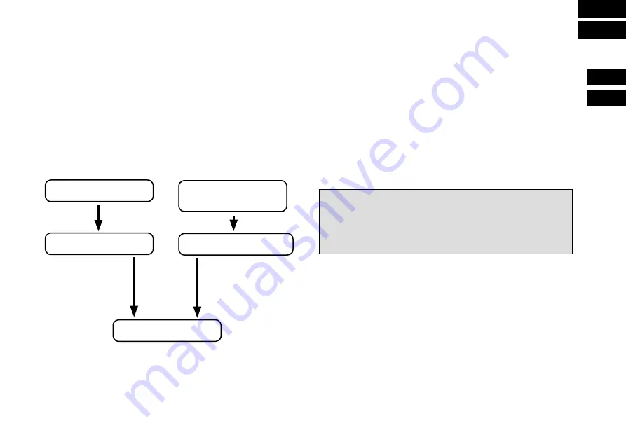
The flow chart below shows the basic operating procedures. 
You  need  to  set  the  frequency,  activate  the  frequency,  and 
receive or transmit. 
There are two ways to set the frequency. Refer to page 5 and 
6 for details.

• Set the frequency normally  

• Set the frequency directly

Set the frequency normally

Set the desired frequency which will be used for the next op-
erating frequency in the standby frequency display. Then ex-
change the active frequency for the standby frequency.

Set the frequency directly

You can directly enter the desired frequency.
Refer to ‘Directly setting the frequency.‘

TIP:


For quick frequency setting, you can enter often-used 

frequencies into memory channels. Refer to “MEMORY OP-
ERATION” for details. (pp. 7–13)
When you recall a memory channel, the previous standby 
frequency is erased.

  Set the standby frequency.

  Activate the frequency.

  Enter the direct frequency 
  setting mode.

  Set the operating frequency.

Receive/transmit

Summary of Contents for IC-A220

Page 1: ...VHF AIR BAND TRANSCEIVERS INSTRUCTION MANUAL This device complies with Part 15 of the FCC Rules Operation is subject to the condition that this device does not cause harmful interference iA220E iA220 ...

Page 2: ...ncy energy and if not installed and used in accordance with the instruction manual may cause harmful interference to radio communi cations Operation of this equipment in a residential area is likely to cause harmful interference in which case the user will be required to correct the interference at his own expense POUR LES RAYONNEMENTS NON INTENTIONNELS DE CLASSE A Cet équipement a été testé et re...

Page 3: ...our ears If you experience ringing reduce the volume level or discontinue use R WARNING NEVER connect the transceiver to an AC outlet or to a power source of more than 28 V DC Such a connection will damage the transceiver CAUTION NEVER connect the transceiver to a power source that is DC fused at more than 10 A Accidental reverse connection will be protected by this fuse higher fuse values will no...

Page 4: ...er l émetteur récepteur avec un casque ou d autres accessoires audio ayant un volume trop élevé Un volume continu trop fort peut entraîner un bour donnement dans vos oreilles Si vous entendez une sonnerie baissez le niveau sonore ou interrompez l utilisation R NE JAMAIS relier l émetteurrécepteur à une prise d alimentation de plus de 28 V Un tel branchement endom magerait votre émetteur récepteur ...

Page 5: ...t be mounted at least 40 centimeters away from the nearest edge of the vehicle in order to protect against exposure to bystanders To ensure that your exposure to RF elec tromagnetic energy is within the FCC al lowable limits for occupational use always adhere to the following guidelines DO NOT operate the radio without a proper antenna at tached as this may damage the radio and may also cause you ...

Page 6: ...on à une énergie électromagnétique de RF se situe dans les limites permises par la FCC pour une utilisation grand public veuillez en tout temps respecter les directives suivantes NE PAS faire fonctionner la radio sans qu une antenne appropriée y soit fixée car ceci risque d endommager la radio et causer une exposition supérieure aux limites établies par la FCC L antenne ap propriée est celle qui e...

Page 7: ...g Regular memory Group memory channels 8 Selecting a weather memory channel 12 History memory channel 12 Selecting a GPS memory channel 13 Editing GPS memory 13 Protecting memory 13 4 OTHER FUNCTIONS 14 Dualwatch operation 14 Priority watch 14 Using the lock function 15 Accessing the 121 5 MHz emergency frequency 15 Enabling the intercom 16 Opening the squelch for test 16 Setting the frequency ste...

Page 8: ...ower ON or OFF Adjusts the audio output level The volume level bar is displayed while rotating VOL Hold down for two seconds to enter the AM squelch level SQL LEVEL item in the Settings menu p 6 Push to set the squelch test function ON or OFF p 16 When the squelch test function is ON and the Auto squelch AUTO SQL item in the Configuration menu p 22 is set to USER SET push VOL again to switch the s...

Page 9: ...tor is used to automatically adjust DISP LOW or DISP HIGH pp 23 24 when the DISP MODE p 23 is set to AUTO i INNER Small TUNING DIAL DIAL Rotate to set the standby frequencies kHz digit p 5 memory channels p 8 and menu mode settings pp 18 19 Hold down for two seconds to turn ON the dial panel lock mode p 15 o OUTER Large TUNING DIAL O DIAL Rotate to set the standby frequency MHz digit p 5 group mem...

Page 10: ...lected p 8 Displays GRP01 GRP05 when the group memory channel is selected p 8 The group name is also displayed if the name has been entered Displays HISTORY when the history memory chan nel is selected p 12 Displays WEATHER when the weather memory chan nel is selected p 12 For only U S A version transceivers Displays GPS when the GPS memory channel is se lected p 13 A third party GPS receiver is r...

Page 11: ...or the next op erating frequency in the standby frequency display Then ex change the active frequency for the standby frequency Set the frequency directly You can directly enter the desired frequency Refer to Directly setting the frequency TIP For quick frequency setting you can enter often used frequencies into memory channels Refer to MEMORY OP ERATION for details pp 7 13 When you recall a memor...

Page 12: ...iving a signal RX is displayed and audio is heard Rotate VOL to adjust the audio level Adjust the squelch if necessary Refer to Squelch settings for de tails 134 805 126 40 RX Transmitting 4 Hold down PTT switch and then speak at your normal q q voice level TX is displayed DO NOT hold the microphone too closely to your mouth or speak too loudly This may distort your signal 134 805 126 40 TX Releas...

Page 13: ...ting mode Directly setting the frequency Squelch settings Adjusting the squelch D D Adjust the squelch to mute undesired noise when no signal received Hold down q q VOL for two seconds to enter SQL LEVEL Rotate w w DIAL to select the desired squelch level to be tween 10 and 10 Push e e RCL to exit SQL LEVEL Switching the squelch mode D D You can switch the squelch mode when the Auto squelch AUTO S...

Page 14: ... channels GRP01 GRP05 There are up to 50 group channels with 10 channels in each of 5 groups Weather memory channels WEATHER 10 weather memory channels can be selected These are used for monitoring NOAA National Oceanic and Atmospheric Administration broadcasts For only U S A version transceivers History memory channels HISTORY Up to 20 history memory channels can be selected The active frequency ...

Page 15: ...g the group memory channel is the only option DONE Returns to the memory mode Push q q RCL to enter the mem ory mode The memory channel number is displayed The memory channel name is also displayed if it has been en tered Rotate w w O DIAL to select the memory channel types For the group memory channel push DIAL and then rotate O DIAL to select a group Rotate e e DIAL to select the de sired channe...

Page 16: ... Enter frequencies into memory channels To enter frequencies into memory channels follow the steps below Rotate q q DIAL and O DIAL to set the desired frequency for the standby frequency Push w w RCL to enter the memory mode The memory channel number is displayed The memory channel name is also displayed if it has been en tered Rotate e e O DIAL to select a desired memory channel Select regular me...

Page 17: ...nnels The memory groups can display a six character name in ad dition to the group number GRP01 GRP05 Push q q RCL to enter the memory mode and then rotate O DIAL to select the group memory channel Push w w DIAL and then rotate O DIAL to select a memory group from GRP01 to GRP05 Push DIAL again to set the memory group Push e e MEM and then rotate O DIAL to select GRP NAME Push r r MEM The channel ...

Page 18: ...e Push t t MEM to set the channel tag Hold down y y RCL to exit the memory mode CH01 127 005 122 00 GRP01 TWR Channel tag list TAG NAME DISPLAY MEANS Group 1 GPS 2 _ _ _ YES Non tag TWR YES YES Tower GND YES YES Ground ATS YES YES ATIS ATF YES YES Air traffic APP YES YES Approach ARR YES YES Arrival AWS YES YES Automatic Weather Station CLR YES YES Clearance Delivery CTF YES YES Common Traffic Adv...

Page 19: ...50 MHz WX06 162 500 MHz WX02 162 400 MHz WX07 162 525 MHz WX03 162 475 MHz WX08 161 650 MHz WX04 162 425 MHz WX09 161 775 MHz WX05 162 450 MHz WX10 163 275 MHz For only U S A version transceivers History memory channel The transceiver has 20 history memory channels When pushing the standby frequency is stored into a history memory channel The frequencies are stored into the history memory channel ...

Page 20: ...ring the frequency data Editing GPS memory The received GPS memory data is stored in the desired group memory channel Push q q RCL to enter the memory mode Rotate w w O DIAL to select GPS GPS is displayed Push e e MEM to enter the GPS memory channel edit mode then rotate O DIAL to select a desired group memory GPS and airport code blink Push r r MEM to store the GPS memory channel data to the sele...

Page 21: ...n receiving a signal or the squelch opens Push w w DUAL again to exit Dualwatch operation DUAL disappears Priority watch The Priority watch operation monitors the active frequency at certain intervals even when receiving a signal on the standby frequency When a signal is received on the active frequency and standby at the same time the transceiver pref erentially receives the active frequency and ...

Page 22: ... be activated even if the key lock function is in use Hold down q q EC for two seconds to set the emergency fre quency 121 50 MHz in direct frequency setting mode EC is displayed 121 505 EC Hold down w w to return to the normal frequency display mode and then push to exchange emergency fre quency with the standby frequency Set the frequency other than 121 500 MHz before pushing to the standby freq...

Page 23: ...tion RX and TEST are displayed To turn the function OFF push w w VOL again RX and TEST disappear Setting the frequency step You can select Frequency steps of 8 33 kHz or 25 kHz in the menu mode Hold down q q RCL for two seconds to enter the Settings menu Rotate w w O DIAL to select FREQ STEP Rotate e e DIAL to select the desired frequency steps of 8 33 kHz or 25 kHz Push r r RCL to exit the Settin...

Page 24: ...hange the scan direction turn DIAL The scan continues even when receiving a signal on the active frequency 162 555 122 00 RX WEATHER SEARCH When receiving a signal on the weather channel e e RX blinks on the standby frequency display and the scan is cancelled DUAL is displayed on the active frequency display WEATHER 161 655 122 00 RX DUAL RX WX08 When no signal is received on the weather channel r...

Page 25: ...w RCL for two seconds to enter the Settings menu Rotate e e O DIAL to select setting items Rotate r r DIAL to select a desired setting Push t t RCL to exit the Settings menu SETTINGS SQL LEVEL 010 01 44 RCL MEM OFF VOL PUSH TEST COMM DUAL EC 010 009 009 010 Desired setting FM SQL LV HP LEVEL INCOM LV1 SQL LEVEL Settings items Settings menu items Items number Setting value Settings menu items Item ...

Page 26: ...9 030 Desired setting MIC1 SQL MIC2 SQL DW INTERVAL AUTO SQL Configuration items Configuration menu items Items number Setting value Configuration menu items Item Ref Item Ref AUTO SQL p 22 DISP HIGH p 24 SQL SW p 22 DISP RESP p 24 MIC1 SQL p 22 U 1 ID SET p 24 MIC2 SQL p 22 U 2 ID SET p 24 DW INTERVAL p 22 AUX IN p 24 PRI WATCH p 22 AUX MAX LEVEL p 24 PW INTERVAL p 22 INCOM MODE p 24 MEM PROTECT ...

Page 27: ... Sets the headphone output level while receiving AF gain The output level is the same as VOL OFF 0 Mutes the headphone 001 to 080 Sets the audio level to between 1 and 80 D D Intercom 1 microphone audio input level IN COM LV1 Sets the intercom 1 microphone input level OFF 0 Mutes the intercom1 microphone 001 to 080 Sets the intercom1 input level to between 1 and 80 D D Intercom 2 microphone audio ...

Page 28: ... OLED ON The 1 kHz digit is always displayed on the OLED ZERO SUPP The 1 kHz digit is displayed only when the 1 kHz digit frequency is 5 kHz D D External input level AUX LEVEL Sets the external input level Displayed only when the External input AUX IN item in the Configu ration menu p 24 is set to ON or INCOM OFF 0 The external input is disabled 001 to 080 Sets the external input level to between ...

Page 29: ...Set Intercom 2 s squelch level The setting level is required to open the squelch when speak ing into Intercom 2 OFF 0 Turns off Intercom 2 s squelch 001 to 030 Sets Intercom 2 s squelch level to between 1 and 30 D D Dualwatch interval DW INTERVAL Sets the interval time while operating Dualwatch or weather scan FAST Sets the interval to 300 milliseconds MID Sets the interval to 600 milliseconds SLO...

Page 30: ...mmer in the Manual dimmer control DISP MAN item p 21 D D Dimmer auto mode DISP AUTO Sets the method to automatically control the dimmer bright ness Displayed only when the Dimmer mode DISP MODE item in the Configuration menu is set to AUTO PHOTO Controls the dimmer brightness by using the light sensi tive detector p 2 EXT Controls the dimmer brightness by using an external volt age D D External di...

Page 31: ...e characters for the tag name t Push MEM again to store the name and exit the edit mode D D External input AUX IN Set the audio usage input from an external audio device Refer to INSTALLATION GUIDE for an external audio device connection details OFF The external audio is not used ON The external audio is output from the connected head set while no signal is received INCOM The external audio is out...

Page 32: ...nterlock mode is not displayed when the TX RX INTERLOCK SW item is set to DISABLE Ask your dealer for the TX RX INTERLOCK SW setting details D Remote exchange REM SWAP Sets the remote control p 16 to use the frequency exchange switch or not OFF The remote control for the frequency exchange switch is OFF ON The remote control for the frequency exchange switch is ON D Remote incom REM INCOM Sets the...

Page 33: ... of the transceiver on the ground A built in speaker and microphone are included Dimensions 200 W 200 H 300 D mm 7 9 W 7 9 H 11 8 D in Outputs 13 8 V DC 6 A Approved Icom optional equipment is designed for optimal performance when used with an Icom transceiver Icom is not responsible for the destruction or damage to an Icom transceiver in the event the Icom transceiver is used with equipment that ...

Page 34: ... V 27 50 V DC negative ground Dimensions 160 W 34 H 271 D mm projections not included 6 3 W 1 3 H 10 7 D inches Weight approximately 1 0 kg 2 2 lb Transmitter D D Output power IC A220 8 W Carrier power IC A220E 6 W Carrier power Spurious emissions IC A220 60 dBc IC A220E 36 dBm harmonics 46 dBm non harmonics Microphone impedance 600 ø Modulation limiting IC A220 70 Maximum 98 IC A220E 85 Maximum 9...

Page 35: ...0583 8 33 118 060 118 0667 8 33 118 065 118 0750 8 33 118 080 118 0833 8 33 118 085 118 0917 8 33 118 090 118 1000 8 33 118 105 These tables show just the display example between 118 0000 MHz and 118 1000 MHz Not show all frequencies in the band are shown Selectivity with 8 33 kHz channel spacing IC A220 6 dB 2 778 kHz 60 dB 7 37 kHz IC A220E 6 dB 2 8 kHz Spurious response rejection IC A220 More t...

Page 36: ...29 Spain ES 13 Hungary HU 30 Sweden SE 14 Iceland IS 31 Switzerland CH 15 Ireland IE 32 Turkey TR 16 Italy IT 33 United Kingdom GB 17 Latvia LV ISO 3166 1 Disposal The crossed out wheeled bin symbol on your product literature or packaging reminds you that in the European Union all electrical and electronic products batteries and accumulators rechargeable batteries must be taken to des ignated coll...

Page 37: ... Directly setting the frequency 6 Dualwatch 14 Dualwatch interval 22 E Emergency frequency 15 Enter frequencies into memory channels 9 Entering channel names 10 Entering group names 10 External dimmer control 23 External input 24 External input gain 24 External input level 21 F FM squelch level 20 Frequency display 21 Frequency step 16 21 Front panel 1 Function display 3 G GPS memory channel 13 Gr...

Page 38: ...ory protection 22 Microphone 1 Gain 21 Microphone 2 Gain 21 O Options 26 P Priority watch 14 Priority watch interval 22 Protecting memory 13 R Rear panel 2 Receiving 5 Regular memory 8 Remote control 16 Remote exchange 25 Remote incom 25 Remote recall 25 S Settings menu items 20 Settings menu 18 Sidetone level 21 Specifications 27 Squelch settings 6 Squelch test 16 Squelch mode 20 T Time Out Timer...

Page 39: ...32 MEMO ...

Page 40: ...A 7210D 1EX q Printed in Japan 2015 Icom Inc Printed on recycled paper with soy ink 1 1 32 Kamiminami Hirano ku Osaka 547 0003 Japan ...

Reviews: