


TIPS FOR THE USB PORT SETTINGS
5
Recent PCs have a USB port instead of an RS-232C port. To
allow an easier connection and mutual communication, a USB
port is also built into the transceiver.
With using an RS-232C communication port, signal lines such as
RTS and DTR are needed to exchange data between the PC and
the transceiver. However, there are no DTR and RTS terminals
on a USB port.
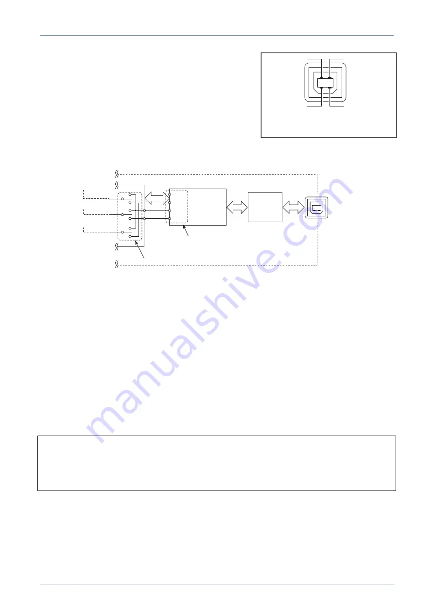
RTS and DTR terminals of the RS-232C can be found in the
Serial-USB converter as shown in Figure 1-6. The data from the [USB B] port is output to these terminals in
this Serial-USB converter.
Figure 1-6 Data bus line between CPU and USB
The RTTY/logging software application sets the output terminal, either RTS or DTR, for each SEND and
CW/RTTY keying signal.
In other words, the software sets the SEND and CW/RTTY keying signal output
terminal of the Serial-USB Converter inside the transceiver.
On the other hand, the transceiver’s set mode items, "USB SEND," "USB keying (CW)", and "USB keying
(RTTY)," selects either the RTS or DTR port of the Serial-USB Converter to capture SEND, CW/RTTY
keying signal, respectively. (Except "OFF")
Therefore, the settings will succeed when the same terminal is set between the transceiver’s “USB SEND,”
“USB keying (CW),” and “USB keying (RTTY)” and software’s SEND, CW keying, and RTTY keying,
respectively.
Note that the setting item name may differ, depending on the software being used.
For example, “PTT” or “Transmit” may be used instead of “SEND,” “FSK” may be used instead of “RTTY.”
Therefore, properly set these items by also referring to the software manual or help files.
For your information:
The “USB SEND” item is a setting to switch the transceiver’s transmit and receive. So, the terminal must be
set to the same setting as that in the software. If a different terminal or OFF is set in the transceiver’s set
mode, the software cannot toggle between transmit and receive.
Note that the transceiver will transmit when the USB SEND line inside the transceiver’s CPU becomes High.
(The transceiver transmits with the inverted logic from the SEND jack, or SEND line of [ACC].)
RS-232C ports of the
Serial-USB Converter
SEND
CW Keying
RTTY Keying
[USB]
CPU
RXD
TXD
RTS
DTR
Serial-USB
Converter
USB
HUB
Sets these switches
Rear panel
(Front view)
Figure 1-5 USB port pin assignment
V
BUS
–DATA
+DATA
GND


