1
ST
Cool
2
ND
Cool
1
ST
Heat
2
ND
Heat
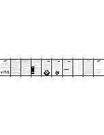
Heat/Cool
Y1,G
YI,Y2,G
W1,G*
W1,W2,G*
Heat Pump (One Compressor)
Y1,G,O
Y1,G,O
Y1,G,B
Y1,W2,G,B
Heat Pump (Two Compressors)
Y1,G,O
Y1,Y2,G,O
Y1,G,B
Y1,Y2,G,B
Emergency Heat (Heat Pump Only)
N/A
N/A
W2,G
W2,G
* G not energized when configured as a gas/oil system
Configuration Mode
OFF
PM
1 . Verify the SC5811 is in the
OFF
mode .
Press the
SYS
(left) button until off mode displays .
2 . Remove the cover of the thermostat by gently pulling near one of the
corners at the top of the thermostat .
3 . Press the
CONFIG
button for 1 second while the SC5811 is in
OFF
mode .
To exit configuration mode, press the
CONFIG
switch for 1 second .
Press the
up
or
down
button to change settings within each screen .
Down
button
Up
button
Press the
right
button to advance to the next screen .
Note:
Pressing the
left
button will return you to the previous screen .
Left
button
Right
button
The configuration mode is used to set the SC5811 to match your heating/cooling system . The SC5811
functions with heat pump, air conditioning, gas, oil or electric heat systems .
To configure the SC5811, perform the following steps:
CONFIG
S1 S2 R
C
W
O/B
G
Y1 W2
W3
Y2
RESET
CONFIG
FP