


71
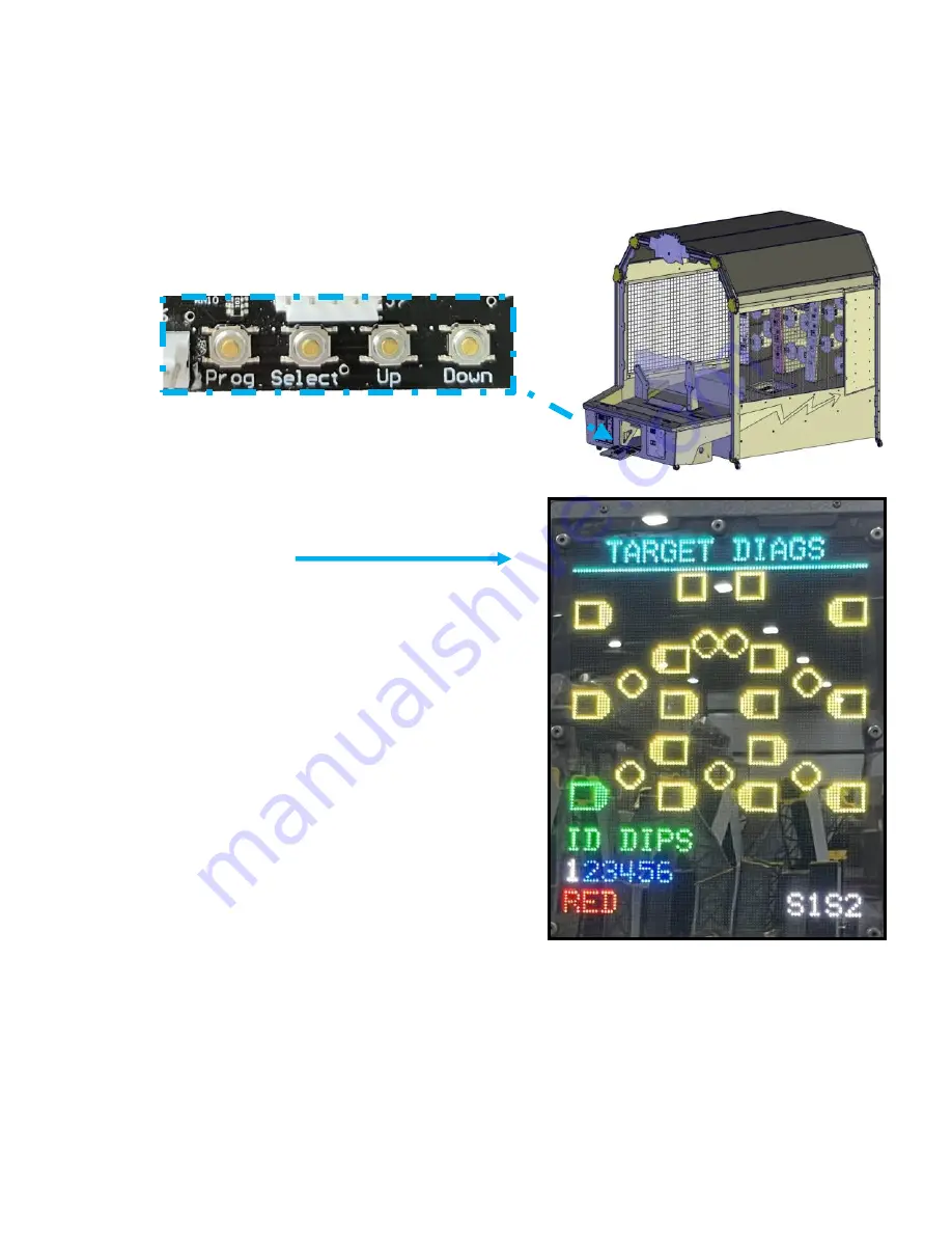
In diagnostics, the Jumbotron will show the layout
of the sensor boards.
It will light the location of the board in green when
elected. You will notice the remainder of the sensors are
yellow. This indicates the remaining boards are sending
and receiving information. If you see any red, this would
indicate the board in that location is not receiving or
sending information.
Diagnostics and trouble shooting guide
Your game comes with extensive diagnostics to aid you in keeping your game running correctly.
To access the diagnostics, open the left lower door assembly.
Press the “SELECT” and “DOWN” buttons at the same time in attract mode.
GAME MUST BE IN ATTRACT MODE TO ENTER DIAGNOSTICS
GREEN
= Selected Sensor board.
YELLOW
= Communication is established.
RED
= No communication:
check power
RJ45 for proper connections
You will also notice the numbers under “ID DIPS”. This indicates the proper dip switch setting for
this location. IT IS NOT READING THE DIPSWITCHES! It is only showing you the proper settings
for that location. White means it should be set to on while blue means it should be set to off.
At the bottom of the screen, it will show you which RGB color the target should be. It will cycle from
Red to green to blue and repeat.
S1 and S2 have different meanings depending on which sensor you are testing.
More details on this later on.
Summary of Contents for DB1200X
Page 7: ...7 Assembly for Steps 1 8 Chapter 1...
Page 16: ...16 Assembly for Steps 9 16 Chapter 2...
Page 22: ...22 Assembly for Steps 17 22 Chapter 3...
Page 28: ...28 Assembly for Steps 23 26 Chapter 4...
Page 33: ...33 Assembly for Steps 27 43 Chapter 5...
Page 43: ...43 Assembly for Steps 44 51 Chapter 6...
Page 48: ...48 Assembly for Steps 52 59 Chapter 7...
Page 53: ...53 STEP 57 Tower harnesses Insert cables from each tower assembly into the bottom holes B...
Page 75: ...75 Tower Covers Part Numbers...
Page 76: ...76 DECAL PART NUMBERS...
Page 82: ...82 DB3277X ball gate Assembly NS1022 P802 black NS1022 P509 blue ZS2015X Actuator...


