background image


2  Installation 

Important  


Before the installation, please make sure the installation surface can sustain at 
least 3X weight of the bracket and the camera.  
 

2.1  Device Installation 

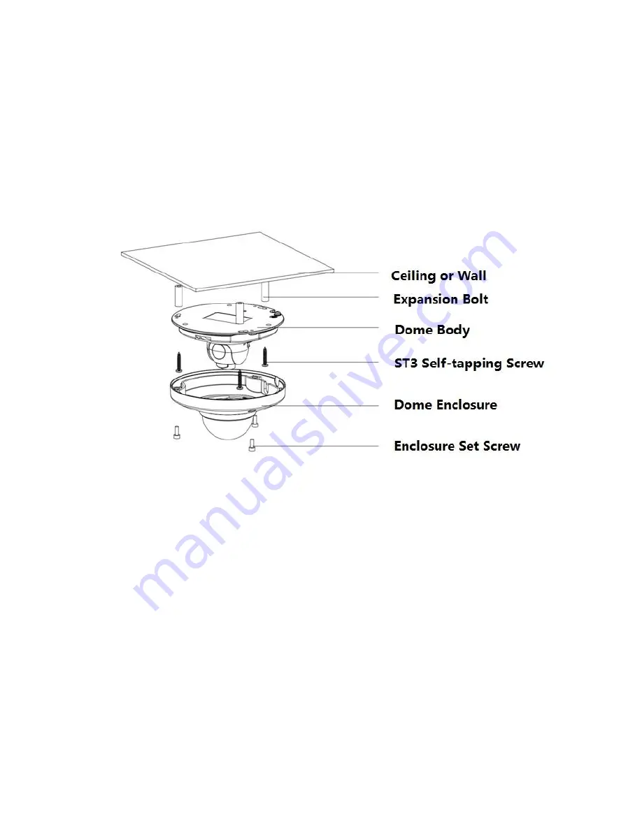
Please refer to Figure 2- 1 for device installation information.  


Figure 2- 1 

Step 1 

Use the inner hex wrench from the accessories bag to unfasten the 3 hex screws on the dome camera 

enclosure and then open the dome enclosure. 


Step 2 

Take the installation position diagram from the accessories bag and then paste it on the installation 

ceiling or the wall according to the monitor area. Please dig three bottom holes of the plastic 

expansion bolts according to the diagram. Take three expansion bolts from the accessories bag and 

then insert them to the holes you just dug and then fix firmly. 

Note:  

If you need to dig a hole to pull through the cable on top of installation surface, you need to dig a cable 

exit hole on the installation surface according to the installation positioning diagram.  

If you need to pull through the cable on the side, you need to dig through the U-shape exit hole on the 

side of chassis to form a cable access, and then pull the cable through the side exit hole on the 

chassis.  


Step 3 

Summary of Contents for ICIP360L4

Page 1: ...i HD Fisheye Panorama Network Camera Quick Start Guide Version 1 0 0 ...

Page 2: ...wer supplying sources to the device at the same time it may result in device damage We assume no liability or responsibility for all the fires or electrical shock caused by improper handling or installation We are not liable for any problems caused by unauthorized modification or attempted repair 2 Environment Please don t aim the device at strong light such as lighting sunlight and so on to focus...

Page 3: ...tergent first and then use it to clean the device Finally use the dry cloth to clean the device Don t use volatile solvent like alcohol benzene thinner and etc or strong detergent with abrasiveness otherwise it will damage the surface coating or reduce the working performance of the device Dome cover is an optical device please don t touch or wipe cover surface directly during installation and use...

Page 4: ... documentation There may be deviation between the actual value of some data and the value provided in the manual due to the reasons such as the real environment is not stable and so on Please refer to the company s final explanation if there is any doubt or dispute The company is not liable for any loss caused by the operation which is not followed by the manual Before installation please open the...

Page 5: ... PC end to Device end 3 1 4 Alarm Setup 4 2 Installation 5 2 1 Device Installation 5 2 2 Micro SD Card Installation 6 3 Quick Configuration Tool 8 3 1 Overview 8 3 2 Operation 8 4 Web Operation 10 4 1 Network Connection 10 4 2 Login and Main Interface 10 4 3 Panorama Function on Web 11 1 Appendix Toxic or Hazardous Materials or Elements 12 ...

Page 6: ...1 1 for more details about external cable functions SN Port Port name Connector Function Description 1 LAN Network port Ethernet port Connect standard Ethernet cable 2 POWER Power input port Connect DC 12V power input power 3 AUDIO OUT Audio output port RCA Output audio signal to speaker and other devices 4 AUDIO IN Audio input port RCA Input audio signal receive analog audio signal from pick up a...

Page 7: ...1 ALARM_IN1 Alarm input port receive the on off signal from external alarm source 2 ALARM_OUT1 Alarm output port output alarm signal to alarm device 3 ALARM_GND GND Sheet 1 2 1 2 Dimensions You can refer to the following figures for dimension information The Unit is mm See Figure 1 3 Figure 1 and Figure 1 Figure 1 3 Figure 1 4 ...

Page 8: ...e the voice info sent via earphone and other devices at the pc end 1 3 2 PC end to Device end Device Connection Please connect the speaker or the MIC to the audio input port of the PC and then connect the earphone to the audio output port of the device Login the Web and then click the Talk button to enable the bidirectional talk function You can see the button becomes orange after you enabled the ...

Page 9: ...resistance to 3 3V Step 3 Open WEB and set corresponding alarm input and output in the alarm setup Please set the alarm input of the WEB end to the alarm input of I O port cable of the corresponding device Then set corresponding NO NC input according to the high low level signal generated when alarm occurs to the alarm input device Step 4 Set the WEB alarm output The alarm output is for the alarm ...

Page 10: ... on the installation ceiling or the wall according to the monitor area Please dig three bottom holes of the plastic expansion bolts according to the diagram Take three expansion bolts from the accessories bag and then insert them to the holes you just dug and then fix firmly Note If you need to dig a hole to pull through the cable on top of installation surface you need to dig a cable exit hole on...

Page 11: ...se refer to Micro SD card installation steps if you need to install Micro SD card and operate step 4 after the installation Connect the host GND to ground lead which may improve device reliability The GND locates next to exit hole on the rear side of the chassis and the GND screw is M3 Figure 2 2 2 2 Micro SD Card Installation Take down the 3 hex screws on the upper enclosure by using the inner he...

Page 12: ...7 Figure 2 3 ...

Page 13: ...can go to the corresponding web login interface Figure 3 1 If you want to modify the device IP address without logging in the device web interface you can go to the configuration tool main interface to set please select a device IP address and then double click it to open the login interface Or you can select an IP address and then click the Login button to go to the login interface See Figure 3 2...

Page 14: ...iguration tool main interface is shown as below See Figure 3 Figure 3 3 For detailed information and operation instruction of the quick configuration tool please refer to the Quick Configuration Tool User s Manual included in the resources CD ...

Page 15: ... Use order ping network camera address to check connection is OK or not 4 2 Login and Main Interface Open IE and input network camera address in the address bar For example if your camera IP is 192 168 1 108 then please input http 192 168 1 108 in IE address bar See The login interface is shown as below See Figure 4 1 Please input your user name and password Default factory name is admin and passw...

Page 16: ...rama Function on Web There is a panorama icon at the lower left corner of web interface and you can click it to view installation mode and display mode at the right Please configure corresponding installation mode on the WEB config page according to the exact installation way Otherwise abnormity may happen to the video display ...

Page 17: ...e toxic or hazardous substance or elements contained in products will not leak or mutate so that the use of these substances or elements will not result in any severe environmental pollution any bodily injury or damage to any assets The consumer is not authorized to process such kind of substances or elements please return to the corresponding local authorities to process according to your local g...

Reviews: