background image

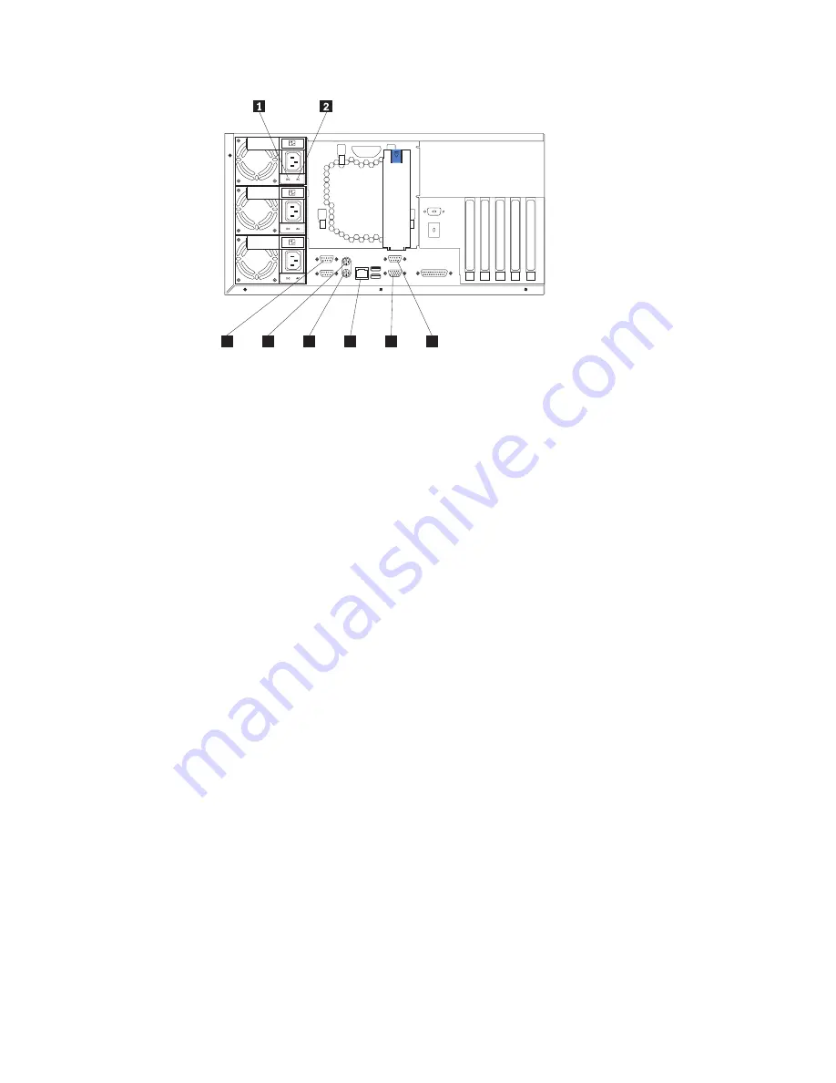
1

AC Power LED

This LED provides status information about the power supply. During
normal operation, both the AC and DC Power LEDs are on.

2

DC Power LED

This LED provides status information about the power supply. During
normal operation, both the AC and DC Power LEDs are on.

3

Serial Port A

4

Mouse

5

Keyboard

6

Ethernet port

7

Video

8

Management

3

4

5

6

7

8

Figure 22. Model 225 rear view

38

IBM TotalStorage

Network Attached Storage 200 Installation Guide

Summary of Contents for totalstorage 200

Page 1: ...IBM TotalStorage Network Attached Storage 200 Models 200 and 225 Hardware Installation Guide ...

Page 2: ......

Page 3: ...IBM TotalStorage Network Attached Storage 200 Models 200 and 225 Hardware Installation Guide ...

Page 4: ...A form for reader s comments is provided at the back of this publication If the form has been removed you may address your comments to International Business Machines Corporation Design Information Development Department CGFA PO Box 12195 Research Triangle Park NC 27709 9990 U S A You can also submit comments to www ibm com networking support feedback nsf docsoverall When you send information to I...

Page 5: ...list 5 Setting up the appliance 5 Setting up the Model 200 5 Setting up the Model 225 6 Setting up the Model 225 in a rack 6 Installing optional features 11 Installing a 5194 EXU storage unit 11 Installing a hot swap hard drive 12 Installing memory modules DIMMs 14 Cabling 20 Starting the appliance 23 Performing initial configuration 25 Chapter 3 Adding and replacing components 27 Before you begin...

Page 6: ...l notices 108 Electronic emission notices 108 Appendix C Getting help service and information 111 Service support 111 Before you call for service 112 Getting customer support and service 112 Getting help online www ibm com storage support nas 112 Getting help by telephone 113 Appendix D Purchasing additional services 115 Warranty and repair services 115 Appendix E Notices 117 Trademarks 118 Append...

Page 7: ...00 40 25 Removing the cover of the Model 225 41 26 Removing the appliance door of the Model 200 42 27 Removing the bezel of the Model 225 43 28 Installing internal drive bays for the Model 200 44 29 Installing internal drive bays for the Model 225 44 30 Installing a hot swap drive 45 31 Replacing a drive in a hot swap drive bay in the Model 200 46 32 Replacing a hot swap power supply 48 33 Removin...

Page 8: ...vi IBM TotalStorage Network Attached Storage 200 Installation Guide ...

Page 9: ...atures of Model 200 and Model 225 2 3 Product Information 5 4 Switches 1 8 33 5 Standard features of ServeRAID 4L and ServeRAID 4H 59 6 IBM Web sites for help services and information 111 7 Telephone numbers for warranted help and information 113 Copyright IBM Corp 2001 vii ...

Page 10: ...viii IBM TotalStorage Network Attached Storage 200 Installation Guide ...

Page 11: ...e 200 hardware installations Safety precautions Be sure to read all caution and danger statements in this publication before performing any of the instructions Leia todas as instruções de cuidado e perigo antes de executar qualquer operação Prenez connaissance de toutes les consignes de type Attention et Danger avant de procéder aux opérations décrites par les instructions Lesen Sie alle Sicherhei...

Page 12: ...r more drive bays power supplies and a network interface Some storage units contain a RAID controller There are no other components in a storage unit and it is accessed by a NAS appliance Notes These notices provide important tips guidance or advice Attention These notices indicate possible damage to programs devices or data An attention notice is placed just before the instruction or situation in...

Page 13: ... any changes that were not available at the time this publication was produced Related publications The following publications contain additional information about the Network Attached Storage 200 v IBM TotalStorage Network Attached Storage 200 User s Reference GA27 4263 v IBM TotalStorage Network Attached Storage 200 Service Guide GA27 0400 v Safety Information 44L2247 Accessibility The softcopy ...

Page 14: ...xii IBM TotalStorage Network Attached Storage 200 Installation Guide ...

Page 15: ...ll for the base model configurations The Model 200 requires two connections power and network Standard features Table 1 lists the standard features of the Model 200 and Model 225 Table 1 Standard Features of the Model 200 and Model 225 Hardware Model 200 Model 225 System v One 800 MHz Intel Pentium III with MMX technology and SIMD extensions v 256 KB Level 2 cache v Integrated 10 100 Ethernet v Fi...

Page 16: ... EXU storage unit storage units each containing 14 Ultra160 36 4 GB hard drives Not an option Option to add up to three additional units 36 4 GB 10K 4 Ultra160 SCSI Hot Swap SL HDD Option to add up to three additional units Includes six standard units 800 133FSB 256 Processor Upgrade Option Standard Note The memory listed below is the total system memory configuration that is available 256 MB 133 ...

Page 17: ...s up to 914 m 2999 ft 10 35 C 50 0 95 0 F at altitudes from 914 m 2999 ft to 2133 m 6998 ft 10 32 C 50 0 89 6 F Humidity 8 80 Nonoperating power off environment Models 200 and 225 Temperature at max altitude of 2133 m 6998 ft 10 43 C 50 0 109 4 F Humidity 8 80 Heat output Approximate heat output for Models 200 and 225 Minimum configuration 683 BTU 200 watts Maximum configuration 2048 BTU 600 watts...

Page 18: ...4 IBM TotalStorage Network Attached Storage 200 Installation Guide ...

Page 19: ...el 225 v Power cords 3 v Recovery CD v Rack mounting kit for Model 225 v Safety Information IBM Part Number 44L2247 If you ordered options for the appliance this package might contain additional hardware or publications for those options If an item is missing or damaged contact your place of purchase Setting up the appliance This section provides information about the initial installation and setu...

Page 20: ...iance and verifying that the power on diagnostics completed successfully see Starting the appliance on page 23 5 Performing the initial configuration see Performing initial configuration on page 25 Setting up the Model 225 in a rack For Model 225 you must first install the appliance in a rack using the rack mounting kit provided The following reduced size illustration of the front and the back of ...

Page 21: ...r Left Slide rail Front Right Slide rail Front Left Slide rail Rear Right Release latch bracket assembly Front Left Release latch bracket assembly Front Right Hinge bracket Rear Right Figure 1 Front and back of the rack mounting template Chapter 2 Installation procedures 7 ...

Page 22: ...vices in a rack appliance appliance The following is a list of items shipped in your rack installation kit If any items are missing or damaged contact your place of purchase Do not place any object weighing more than 82kg 180 lb on top of rack mounted devices Use safe practices when lifting 32 kg 70 5 lb 82 kg 180 lb Cable management assembly Cable straps 7 Cable ties 10 Cage nuts 12 Clip nuts 12 ...

Page 23: ...ils out of the rack Lift the above the rails then rest the rack support wheels located on the rear of the on the slide rails Lower the front of the onto the slide rails Be sure the bracket notches on the front of the fit securely on the tabs located on the front of the slide rails appliance appliance appliance appliance Note A Use the M4 screws to secure the appliance to the rails Unscrew the rack...

Page 24: ...l the cables through the cable management assembly as shown Then use the cable straps or the cable ties to secure the cables to the cable management assembly 9 A B A B B Slide the into the rack until the release latches snap shut Then insert the M6 screws through the release latch bracket assembly Inserting the M6 screws is optional unless you are moving the rack or the rack is in a vibration pron...

Page 25: ... unit to Channel 2 the second to Channel 3 and so forth Notes 1 The ServeRAID 4L and ServeRAID 4H adapters do not support configurations that use both the internal and external connectors on the same channel concurrently For example you cannot use both external Channel 1 and internal Channel 1 2 The battery backup cache protects the data stored in the ServeRAID cache memory during a power outage o...

Page 26: ...ge 11 for the channel connector locations 2 Connect the other end of the SCSI cable to the 5194 EXU storage unit For detailed installation and cabling instructions for the 5194 EXU storage unit refer to the IBM TotalStorage Network Attached Storage 5194 EXU Storage Unit Installation and User s Guide Installing a hot swap hard drive You can install up to three hot swap drives in the Model 200 The M...

Page 27: ...ting your finger into the depression at the left side of the filler panel and pulling it away from the appliance 3 Install the hard disk drive in the hot swap bay a Ensure the tray handle is open that is perpendicular to the drive b Align the rails on the drive assembly with the guide rails in the drive bay c Gently push the drive assembly into the bay until the drive connects to the planar d Push...

Page 28: ...other options that you intend to install v Have a small flat blade screwdriver available v Before you begin installing components read the safety information found in Translated safety notices on page 77 v For translations of the safety notices that are included in this guide refer to Safety Information System reliability considerations To help ensure proper cooling and system reliability make sur...

Page 29: ...o release the cover then slide the cover toward the rear of the appliance about 25 mm 1 in Move the top edge of the cover out from the appliance then lift the cover off the appliance Set the cover aside Attention For proper cooling and airflow replace the cover before switching on the appliance Operating the appliance for extended periods of time over 30 minutes with the cover removed might damage...

Page 30: ... can reach the cables on the back of the appliance 4 Move the cover release lever down while sliding the top cover toward the rear of the appliance about 25 mm 1 in Lift the cover off the appliance and set the cover aside Attention For proper cooling and airflow replace the cover before switching on the appliance Operating the appliance for extended periods of time over 30 minutes with the cover r...

Page 31: ...s refer to Handling electrostatic discharge sensitive devices on page 76 1 Review the safety precautions listed in Statement 1 and Statement 5 in Translated safety notices on page 77 2 Review the documentation that comes with your option 3 Switch off the appliance and peripheral devices and disconnect all external cables and power cords 4 Remove the cover 5 Touch the static protective package cont...

Page 32: ...ion If a gap exists between the DIMM and the retaining clips the DIMM has not been properly installed In this case open the retaining clips and remove the DIMM then reinsert the DIMM 7 Install additional DIMMs in the order specified in the documentation that comes with your option See Figure 7 for memory connector locations 8 Continue with Replacing the cover on page 19 DIMM 2 DIMM 1 DIMM connecto...

Page 33: ... of the cover into the slots at the top of the appliance 3 Hold the cover against the appliance and slide the cover toward the front of the appliance until the cover clicks into place 4 Switch on the appliance 5 The system displays a message indicating that the memory configuration has changed Start the Configuration Setup Utility program and select Save Settings 6 Restart the appliance Slots Left...

Page 34: ...ogram and select Save Settings 5 Restart the appliance Cabling For each of the three power supplies connect one end of the power cord to the power supply and the other end to an appropriate outlet Connect one end of the Gigabit Ethernet cable to the Gigabit Ethernet Adapter located in one of the expansion slots see Figure 10 on page 21 and the other to the system network Note You may use a 10 100 ...

Page 35: ...Serial A Keyboard Service Ethernet Video Cable restraint bracket ServeRAID Gigabit Ethernet Figure 10 Cabling the appliance Chapter 2 Installation procedures 21 ...

Page 36: ...ugh the cable restraint bracket and then route the cables through the cable management assembly on the rack see Figure 11 Cable straps Figure 11 Routing cables through cable management assembly 22 IBM TotalStorage Network Attached Storage 200 Installation Guide ...

Page 37: ... pressing the power button on the front of the appliance Note After you plug the power cord of the appliance into an electrical outlet wait approximately 20 seconds before pressing the power button During this time the system management processor is initializing and the power button does not respond Attention The operating system undergoes a series of initialization operations upon start up The fi...

Page 38: ...ppliance This starts an orderly shutdown of the operating system if this feature is supported by your operating system and places the appliance in standby mode Note After switching off the appliance wait at least 5 seconds before you press the power button to switch on the appliance again v Press and hold the power button for more than 4 seconds to cause an immediate shutdown of the appliance and ...

Page 39: ...Performing initial configuration Refer to the IBM TotalStorage Network Attached Storage Models 200 and 225 User s Reference for software configuration and setup Chapter 2 Installation procedures 25 ...

Page 40: ...26 IBM TotalStorage Network Attached Storage 200 Installation Guide ...

Page 41: ...read the safety information found in Translated safety notices on page 77 For translations of the safety notices that are included in this guide refer to Safety Information System reliability considerations Adding options to the base configurations could increase power requirements beyond the limit for redundancy To ensure that redundancy is maintained check the status of the NON LED on the system...

Page 42: ...liance do not wear cuff links while you are working inside the appliance v Do not allow your necktie or scarf to hang inside the appliance v Remove jewelry such as bracelets rings necklaces and loose fitting wrist watches v Remove items from your shirt pocket such as pens or pencils that could fall into the appliance as you lean over it v Take care to avoid dropping any metallic objects such as pa...

Page 43: ...n your appliance Note The illustrations in this document might differ slightly from your hardware Terminator card Microprocessor Memory module Power supply Fan Adapter retention bracket Adapter support bracket Fan blower Figure 13 Locations of major components Chapter 3 Adding and replacing components 29 ...

Page 44: ... 33 MHz J39 PCI slot 3 64 bit 33 MHz J34 PCI slot 2 32 bit 33 MHz J32 PCI slot 1 32 bit 33 MHz J27 Battery DIMM 1 J23 DIMM 2 J21 DIMM 3 J19 DIMM 4 J18 Microprocessor 2 U17 Microprocessor 1 U3 Voltage regulator module VRM2 U29 Figure 14 System board options connectors 30 IBM TotalStorage Network Attached Storage 200 Installation Guide ...

Page 45: ...signal J51 DASD SCSI system management J5 Power system management and signal J12 Diskette J26 IDE J31 On Off Reset panel J38 Fan 2 J60 Operator information panel J50 Fan 1 unused J59 Fan 3 J35 Figure 15 System board internal cable connectors Chapter 3 Adding and replacing components 31 ...

Page 46: ... for external devices Video Advanced System Management Processor port J13 Ethernet port J9 Keyboard mouse port J6 Serial ports J3 Figure 16 System board external port connectors 32 IBM TotalStorage Network Attached Storage 200 Installation Guide ...

Page 47: ...t the bottom The Off position for each switch is the side nearer the diagnostics panel Table 4 describes the function for each switch Table 4 Switches 1 8 Switch number Switch description 8 Bypass power on password The default setting is Off When toggled to the On position and back to Off clears the power on password if one is set 7 Reserved The default setting is Off 6 Clock frequency selection T...

Page 48: ...upply 2 failure PS3 Power supply 3 failure NON Non redundant power OVER Overspec The system has exceeded the power capabilities of the installed power supply units NMI Non maskable interrupt occurred TEMP System temperature exceeded maximum rating FAN A fan failed or is operating slowly MEM Memory failure One or more memory DIMMS have failed CPU Microprocessor failure One or both microprocessors h...

Page 49: ...liance controls and indicators Figure 19 Figure 20 on page 36 Figure 21 on page 37 and Figure 22 on page 38 illustrate the various controls and indicators on the appliance models Note The Model 200 is also known as the tower model The Model 225 is also known as the rack model 1 Operator Information panel 2 Hard Drive Status LED 3 Hard Drive Activity LED 4 Serial Number 5 Cover Release Latch 6 Rese...

Page 50: ...The LEDs on this panel give status information for your appliance See Operator information panel on page 39 for more information Hard Drive Status LED Each of the hot swap drives has a Hard Drive Status LED When this amber LED is on continuously the drive has failed When the LED flashes slowly one flash per second the drive is being rebuilt When the LED flashes rapidly three flashes per second the...

Page 51: ... DC Power LEDs are on 2 DC Power LED This LED provides status information about the power supply During normal operation both the AC and DC Power LEDs are on 3 Serial Port A 4 Mouse 5 Keyboard 6 Ethernet port 7 Video 8 Management 3 4 5 6 7 8 Figure 21 Model 200 rear view Chapter 3 Adding and replacing components 37 ...

Page 52: ...EDs are on 2 DC Power LED This LED provides status information about the power supply During normal operation both the AC and DC Power LEDs are on 3 Serial Port A 4 Mouse 5 Keyboard 6 Ethernet port 7 Video 8 Management 3 4 5 6 7 8 Figure 22 Model 225 rear view 38 IBM TotalStorage Network Attached Storage 200 Installation Guide ...

Page 53: ...error occurs A LED on the diagnostic panel on the system board will also be on to further isolate the error Ethernet Transmit Receive Activity LED This green LED is on when there is transmit or receive activity to or from the appliance on the Service Ethernet port Ethernet Link Status LED This green LED is on when there is an active connection on the Service Ethernet port Ethernet Speed LED This g...

Page 54: ...than a hot swap hard disk drive or hot swap power supply switch off the appliance and all attached devices and disconnect all external cables and power cords 3 Slide the cover release lever on the front of the appliance to release the cover then slide the cover toward the rear of the appliance about 25 mm 1 in Move the top edge of the cover out from the appliance then lift the cover off the applia...

Page 55: ...ock Note When the appliance is in the locked position you can reach the cables on the back of the appliance 4 Move the cover release lever down while sliding the top cover toward the rear of the appliance about 25 mm 1 in Lift the cover off the appliance and set the cover aside Attention For proper cooling and airflow replace the cover before switching on the appliance Operating the appliance for ...

Page 56: ...e door up and off the hinge Set the door aside in a safe place To remove the bezel 1 Move the blue bezel release lever following the curve of the lever opening 2 Lift the bezel tabs out of the slots and pull the bezel away from the appliance front Store the bezel in a safe place Bezel release lever Flange Door Figure 26 Removing the appliance door of the Model 200 42 IBM TotalStorage Network Attac...

Page 57: ...st of supported tape drives at www storage ibm com Installing internal drive bays Internal hard drives are installed in bays The drive bays of the Network Attached Storage 200 are in the front of the appliance as shown in the following illustrations Attention If you are going to install additional hard drives in the non hot swap drive bays you must install the power supply backplane option and add...

Page 58: ...ferred to as hot swap hard drives Non hot swap bay A Non hot swap bay B Non hot swap bay C Non hot swap bay D SCSI ID 0 SCSI ID 2 SCSI ID 3 SCSI ID 4 SCSI ID 8 SCSI ID 9 Hot swap bays Hard disk activity light Hard disk status light Figure 28 Installing internal drive bays for the Model 200 Non hot swap bay A Non hot swap bay B Non hot swap bay C Non hot swap bay D SCSI ID 0 SCSI ID 1 SCSI ID 3 SCS...

Page 59: ...es ESDs take precautions to avoid damage from static electricity For details on handling these devices refer to Handling electrostatic discharge sensitive devices on page 76 1 Remove the filler panel from one of the empty hot swap drive bays by inserting your finger into the depression at the left side of the filler panel and pulling it away from the appliance 2 Install the hard drive in the hot s...

Page 60: ...tain conditions are met 2 Before you remove a hot swap hard drive that is not defective back up all important data 3 To avoid damage to a hard drive pull on the release lever to disengage the hard drive connector from the backplane at the back of the drive bay wait approximately 30 seconds to allow the hard drive to spin down and then completely remove it from the bay Refer to Figure 31 while you ...

Page 61: ... drive connects to the backplane d Push the tray handle toward the closed position until it locks the hard drive in place 6 Check the hard drive status indicators to verify that the hard drive is installed properly the Hard Drive Status LED is located to the immediate right of the hard disk drive v When the amber LED is on continuously the hard drive has failed v When the green LED flashes slowly ...

Page 62: ...r Supply 3 LED PS3 on the system board diagnostics panel refers to this power supply See Figure 18 on page 34 for more information about the diagnostics panel AC Power LED This LED provides status information about the power supply During normal operation both the AC and DC Power LEDs are on Refer to the Power Supply LEDs section in the IBM TotalStorage IP Storage 200i Administrator s Guide for mo...

Page 63: ...ction To remove a hot swap power supply 1 Check the LEDs on the power supplies to determine which power supply has failed If a power supply has failed go to step 4 on page 50 2 Remove the engine covers 3 Check the LEDs on the diagnostics panel on the system board a If the NON non redundant LED is on you do not have redundancy switch OFF the appliance and peripheral devices then continue with step ...

Page 64: ...e Replacing a hot swap power supply on page 51 7 Plug the power cord for the power supply into the power cord connector 8 Verify that the AC Power LED and DC Power LED are on indicating that the power supply is operating correctly 9 If you switched the appliance off in step 3 3a on page 49 switch ON the appliance and peripheral devices Diagnostics panel Figure 33 Removing a hot swap power supply 5...

Page 65: ...lace 2 Install the replacement power supply in the bay a Place the handle on the power supply in the open position that is perpendicular to the power supply and slide the power supply into the chassis b Gently close the handle to seat the power supply in the bay 3 Plug the power cord for the power supply you just installed into the power cord connector 4 Route the power cord through the cable rest...

Page 66: ...SCSI device is attached to channel 1 This means you cannot attach an external SCSI device to channel 1 Note The ServeRAID 4H controller uses the module P N 38L3386 containing a lithium battery Statement 2 CAUTION When replacing the lithium battery use only IBM Part Number 33F8354 or an equivalent type battery recommended by the manufacturer If your system has a module containing a lithium battery ...

Page 67: ...ach any external devices to the ServeRAID 4L controller Note The ServeRAID 4L controller uses the module P N 38L3386 containing a lithium battery Statement 2 CAUTION When replacing the lithium battery use only IBM Part Number 33F8354 or an equivalent type battery recommended by the manufacturer If your system has a module containing a lithium battery replace it only with the same module type made ...

Page 68: ...wer cords and cables from the appliance 3 Remove the appliance cover 4 Remove the expansion slot cover 5 Touch the static protective package containing the controller to an unpainted metal expansion slot cover on the appliance This discharges any static electricity from the package and from your body 6 Remove the controller from the static protective package holding the controller by the edges Do ...

Page 69: ... physical drives to install install them now See your appliance documentation for drive installation instructions Note The ServeRAID controllers use SCSI ID 7 13 Install the appliance cover 14 If you disconnected the cables and power cords in 2 on page 54 reconnect the cables and cords See your appliance documentation if you need detailed instructions 15 If you want to attach an external SCSI devi...

Page 70: ...e 2 Start a browser 3 Go to www ibm com storage support nas 4 Select BIOS and firmware code for the ServeRAID controller 5 Boot the diskettes as directed and follow the instructions on the screen 6 Remove the diskette and reboot the appliance Configuring the ServeRAID Controller Follow these instructions to configure a ServeRAID Controller 1 Attach a keyboard and a monitor to the appliance then sw...

Page 71: ...e the Mini Configuration program 10 Press Ctrl Alt Del to reboot the appliance Installing adapters You can install up to three peripheral component interconnect PCI adapters in the available expansion connectors called slots on the system board of the Model 200 you can install up to four PCI adapters in the Model 225 Your appliance comes with an integrated video controller which is a component on ...

Page 72: ... and use the 64 bit slots for 64 bit adapters v Your appliance uses a rotational interrupt technique to configure PCI adapters Because of this technique you can install a variety of PCI adapters that currently do not support sharing of PCI interrupts v PCI slots 1 and 2 are on PCI bus A and PCI slots 3 4 and 5 are on PCI bus B Note PCI bus A is often referred to as bus 0 PCI bus B is often referre...

Page 73: ...nhanced 5 E5 00 10 1E0 50 0 1 5 Enhanced 1 1E and Enhanced 5 E5 00 10 1E0 50 System PCI data bus 64 bit at 33 MHz 64 bit at 33 MHz To install an adapter Attention When you handle electrostatic discharge sensitive devices ESDs take precautions to avoid damage from static electricity For details on handling these devices refer to Handling electrostatic discharge sensitive devices on page 76 1 Review...

Page 74: ...he adapter manufacturer 9 Install the adapter a If necessary remove the adapter support bracket retaining clip b Carefully grasp the adapter by its top edge or upper corners and align it with the expansion slot on the system board c Press the adapter firmly into the expansion slot Attention When you install an adapter in the appliance be sure that it is completely and correctly seated in the syste...

Page 75: ... clock frequencies and external clock frequencies must be identical Model 200 Attention When you handle electrostatic discharge sensitive devices ESDs take precautions to avoid damage from static electricity For details on handling these devices refer to Handling electrostatic discharge sensitive devices on page 76 1 Review the safety precautions listed in Statement 1 and Statement 5 in Translated...

Page 76: ...devices refer to Handling electrostatic discharge sensitive devices on page 76 1 Review the safety precautions listed in Statement 1 and Statement 5 in Translated safety notices on page 77 2 Switch off the appliance and peripheral devices and disconnect all external cables and power cords then remove the cover see Removing the cover Model 225 on page 41 for details 3 Remove the bad microprocessor ...

Page 77: ...al domestic waste They will be taken back free of charge by the manufacturer distributor or representative to be recycled or disposed of in a proper manner To order replacement batteries call 1 800 772 2227 within the United States Before you begin v Read Before you begin on page 27 v Follow any special handling and installation instructions supplied with the replacement battery Note After you rep...

Page 78: ...ately 20 seconds after you plug the power cord of your appliance into an electrical outlet for the Power Control button to become active 5 Switch on the appliance 6 Start the Configuration Setup Utility program and set configuration parameters v Set the system date and time v Set the power on password v Reconfigure your appliance Figure 43 Replacing the battery Figure 44 Installing the battery 64 ...

Page 79: ... the appliance place the bottom of the cover on the bottom rail of the chassis 2 Insert the tabs at the top of the cover into the slots at the top of the appliance 3 Hold the cover against the appliance and slide the cover toward the front of the appliance until the cover clicks into place Slots Left side cover Figure 45 Replace the Model 200 cover Chapter 3 Adding and replacing components 65 ...

Page 80: ...n the left and right sides of the cover should be on the outside of the appliance chassis 2 Hold the cover against the appliance and slide the cover toward the front of the appliance until the cover clicks into place Flange Flange Top cover Side latches Figure 46 Replacing the Model 225 cover 66 IBM TotalStorage Network Attached Storage 200 Installation Guide ...

Page 81: ...oor 1 Set the door on the bottom hinge 2 Press the flange downward while pressing the top of the door toward the appliance until the flange connects with the top hinge Then release the flange 3 Close and lock the appliance door Attention Be sure to maintain a clearance of at least 127 mm 5 in on the front and rear of the appliance to allow for air circulation Bezel Flange Door Figure 47 Replacing ...

Page 82: ...e you begin on page 27 and the documentation that comes with your options 2 Switch off the appliance and all attached devices 3 Follow the instructions that come with the option to prepare it for installation and to connect it to the appliance Input output connector locations The following illustration shows the input output connectors ports and the expansion slots on the rear of the appliance For...

Page 83: ...ability which enables simultaneous transmission and reception of data on the Ethernet local area network LAN To access the Ethernet port connect a Category 3 4 or 5 unshielded twisted pair UTP cable to the RJ 45 connector on the rear of your appliance Notes 1 The 100BASE TX Fast Ethernet standard requires that the cabling in the network be Category 5 or higher 2 If you plan to use the IBM Advanced...

Page 84: ...imary Ethernet controller detects a link failure all Ethernet traffic associated with it is switched to the redundant secondary controller This switching occurs without any user intervention When the primary link is restored to an operational state the Ethernet traffic switches back to the primary Ethernet controller The switch back to the primary Ethernet controller can be automatic or manually c...

Page 85: ...naissance de toutes les consignes de type Attention et Danger avant de procéder aux opérations décrites par les instructions Lesen Sie alle Sicherheitshinweise bevor Sie eine Anweisung ausführen Accertarsi di leggere tutti gli avvisi di attenzione e di pericolo prima di effettuare qualsiasi operazione Lea atentamente todas las declaraciones de precaución y peligro ante de llevar a cabo cualquier o...

Page 86: ...72 IBM TotalStorage Network Attached Storage 200 Installation Guide ...

Page 87: ...ntatives and the customer s personnel are not in a hazardous position v Place removed covers and other parts in a safe place away from all personnel while you are servicing the machine v Keep your tool case away from walk areas so that other people will not trip over it v Do not wear loose clothing that can be trapped in the moving parts of a machine Ensure that your sleeves are fastened or rolled...

Page 88: ...s or near equipment that has hazardous voltages v Disconnect all power before Performing a mechanical inspection Working near power supplies Removing or installing main units v Before you start to work on the machine unplug the power cord If you cannot unplug it ask the customer to power off the wall box that supplies power to the machine and to lock the wall box in the off position v If you need ...

Page 89: ...self Switch off power Send another person to get medical aid Safety inspection guide The intent of this inspection guide is to assist you in identifying potentially unsafe conditions on these products Each machine as it was designed and built had required safety items installed to protect users and service personnel from injury This guide addresses only those items However good judgment should be ...

Page 90: ...ame charge Notes 1 Use product specific ESD procedures when they exceed the requirements noted here 2 Make sure that the ESD protective devices you use have been certified ISO 9000 as fully effective When handling ESD sensitive parts v Keep the parts in protective packages until they are inserted into the product v Avoid contact with other people v Wear a grounded wrist strap against your skin to ...

Page 91: ...provided in the following languages v English v Brazilian Portuguese v Chinese v French v German v Italian v Korean v Spanish Important All safety notices in the Appliance Library begin with a number This number is used to cross reference an English caution or danger notice with translated versions of the caution or danger notice in this section Be sure to read all safety notices before performing...

Page 92: ...e in the installation and configuration procedures v Connect and disconnect cables as described in the following table when installing moving or opening covers on this product or attached devices To Connect To Disconnect 1 Turn everything OFF 2 First attach all cables to devices 3 Attach signal cables to connectors 4 Attach power cords to outlet 5 Turn device ON 1 Turn everything OFF 2 First remov...

Page 93: ... the device v Use of controls or adjustments or performance of procedures other than those specified herein might result in hazardous radiation exposure DANGER Some laser products contain an embedded Class 3A or Class 3B laser diode Note the following Laser radiation when open Do not stare into the beam do not view directly with optical instruments and avoid direct exposure to the beam Some laser ...

Page 94: ...t turn off the electrical current supplied to the device The device also might have more than one power cord To remove all electrical current from the device ensure that all power cords are disconnected from the power source 1 2 Statement 10 CAUTION Do not place any object weighing more than 82 kg 180 lb on top of rack mounted devices 80 IBM TotalStorage Network Attached Storage 200 Installation G...

Page 95: ...bos e não realize instalação manutenção ou reconfiguração deste produto durante uma tempestade com raios v Conecte todos os cabos de alimentação a tomadas elétricas corretamente instaladas e aterradas v Conecte todos os equipamentos ao qual esse produto será conectado a tomadas corretamente instaladas v Sempre que possível utilize apenas uma das mãos para conectar ou desconectar cabos de sinal v N...

Page 96: ...o for utilizada manuseada e descartada de maneira correta Não v Jogue ou coloque na água v Aqueça a mais de 100 C 212 F v Conserte nem desmonte Para descartar a bateria entre em contato com a área de atendimento a clientes IBM pelo telefone 011 889 8986 para obter informações sobre como enviar a bateria pelo correio para a IBM Instrução 3 PRECAUCIÓN Quando produtos a laser unidades de CD ROM unida...

Page 97: ...s 55 kg 121 2 lbs CUIDADO Ao levantar a máquina faça o com segurança Instrução 5 CUIDADO Os botões Liga Desliga localizados no dispositivo e na fonte de alimentação não desligam a corrente elétrica fornecida ao dispositivo O dispositivo também pode ter mais de um cabo de alimentação Para remover toda a corrente elétrica do dispositivo assegure que todos os cabos de alimentação estejam desconectado...

Page 98: ...CUIDADO Instrução 10 CUIDADO Não coloque nenhum objeto com peso superior a 82 kg 180 lbs sobre dispositivos montados em rack 84 IBM TotalStorage Network Attached Storage 200 Installation Guide ...

Page 99: ...Appendix B Safety and environmental notices 85 ...

Page 100: ...86 IBM TotalStorage Network Attached Storage 200 Installation Guide ...

Page 101: ...Appendix B Safety and environmental notices 87 ...

Page 102: ...88 IBM TotalStorage Network Attached Storage 200 Installation Guide ...

Page 103: ...Appendix B Safety and environmental notices 89 ...

Page 104: ...90 IBM TotalStorage Network Attached Storage 200 Installation Guide ...

Page 105: ...s avec ses versions traduites dans la présente section Par exemple si une consigne de type Attention est précédée du chiffre 1 ses traductions sont également précédées du chiffre 1 dans la présente section Prenez connaissance de toutes les consignes de type Attention et Danger avant de procéder aux opérations décrites par les instructions Appendix B Safety and environmental notices 91 ...

Page 106: ...retirer les carters de l unité mettez celle ci hors tension et déconnectez ses cordons d alimentation ainsi que les câbles qui la relient aux réseaux aux systèmes de télécommunication et aux modems sauf instruction contraire mentionnée dans les procédures d installation et de configuration v Lorsque vous installez ou que vous déplacez le présent produit ou des périphériques qui lui sont raccordés ...

Page 107: ...rieure à 100 C v Ne cherchez pas à la réparer ou à la démonter Pour la mise au rebut reportez vous à la réglementation en vigueur Notice n 3 ATTENTION Si des produits laser sont installés tels que des unités de CD ROM ou de DVD des périphériques contenant des fibres optiques ou des émetteurs récepteurs prenez connaissance des informations suivantes v N ouvrez pas ces produits pour éviter une expos...

Page 108: ...kg ATTENTION Faites vous aider pour soulever ce produit Notice n 5 ATTENTION Le bouton de mise sous tension hors tension de l unité et l interrupteur d alimentation du bloc d alimentation ne coupent pas l arrivée de courant électrique à l intérieur de la machine Il se peut que votre unité dispose de plusieurs cordons d alimentation Pour isoler totalement l unité du réseau électrique débranchez tou...

Page 109: ...ein Sicherheitshinweis mit der Nummer 1 beginnt so erscheint die übersetzung für diesen Sicherheitshinweis in diesem Abschnitt unter dem Hinweis 1 Lesen Sie alle Sicherheitshinweise bevor Sie eine Anweisung ausführen Hinweis 1 VORSICHT Elektrische Spannungen von Netz Telefon und Datenübertragungsleitungen sind gefährlich Aus Sicherheitsgründen v Bei Gewitter an diesem Gerät keine Kabel anschließen...

Page 110: ... Kabel anschlieβen Kabel lösen 1 Alle Geräte ausschalten und Netzstecker ziehen 2 Zuerst alle Kabel an Einheiten anschließen 3 Signalkabel an Anschlußbuchsen anschließen 4 Netzstecker an Steckdose anschließen 5 Gerät einschalten 1 Alle Geräte ausschalten 2 Zuerst Netzstecker von Steckdose lösen 3 Signalkabel von Anschlußbuchsen lösen 4 Alle Kabel von Einheiten lösen Hinweis 2 ACHTUNG Eine verbrauc...

Page 111: ...ellelemente sowie Verfahren nur entsprechend den Anweisungen im vorliegenden Handbuch einsetzen Andernfalls kann gefährliche Laserstrahlung auftreten VORSICHT Manche CD ROM Laufwerke enthalten eine eingebaute Laserdiode der Klasse 3A oder 3B Die nachfolgend aufgeführten Punkte beachten Laserstrahlung bei geöffneter Tür Niemals direkt in den Laserstrahl sehen nicht direkt mit optischen Instrumenten...

Page 112: ...wiegen auf Rack Einheiten ablegen Importante Tutti gli avvisi di attenzione e di pericolo riportati nella pubblicazione appliance Library iniziano con un numero Questo numero viene utilizzato per confrontare avvisi di attenzione o di pericolo in inglese con le versioni tradotte riportate in questa sezione Ad esempio se un avviso di attenzione inizia con il numero 1 la relativa versione tradotta è ...

Page 113: ...ritto nella seguente tabella quando si effettuano l installazione la rimozione o l apertura dei coperchi di questo prodotto o delle unità collegate Per collegare Per scollegare 1 SPEGNERE tutti i dispositivi 2 Collegare prima tutti i cavi alle unità 3 Collegare i cavi di segnale ai connettori 4 Collegare i cavi di alimentazione alle prese elettriche 5 ACCENDERE le unità 1 SPEGNERE tutti i disposit...

Page 114: ...are l assistenza tecnica v L utilizzo di controlli regolazioni o l esecuzione di procedure non descritti nel presente manuale possono provocare l esposizione a radiazioni pericolose PERICOLO Alcuni prodotti laser contengono all interno un diodo laser di Classe 3A o Classe 3B Prestare attenzione a quanto segue Aprendo l unità vengono emesse radiazioni laser Non fissare il fascio non guardarlo diret...

Page 115: ...tatore non disattiva la corrente elettrica fornita all unità L unità potrebbe disporre di più di un cavo di alimentazione Per disattivare la corrente elettrica dall unità accertarsi che tutti i cavi di alimentazione siano scollegati dalla sorgente di alimentazione 1 2 Avviso 10 ATTENZIONE Appendix B Safety and environmental notices 101 ...

Page 116: ...Non poggiare oggetti che pesano più di 82 kg sulla parte superiore delle unità montate in rack 102 IBM TotalStorage Network Attached Storage 200 Installation Guide ...

Page 117: ...Appendix B Safety and environmental notices 103 ...

Page 118: ... evitar una descarga eléctrica v No conecte ni desconecte ningún cable ni realice las operaciones de instalaciín mantenimiento o reconfiguraciín de este producto durante una tormenta v Conecte cada cable de alimentaciín a una toma de alimentaciín eléctrica con conexiín a tierra y cableado correctos v Conecte a tomas de alimentaciín con un cableado correcto cualquier equipo que vaya a estar conecta...

Page 119: ...io utilice únicamente el número de pieza 33F8354 de IBM o cualquier tipo de batería equivalente que recomiende el fabricante Si el sistema tiene un mídulo que contiene una batería de litio sustitúyalo únicamente por el mismo tipo de mídulo que ha de estar creado por el mismo fabricante La batería contiene litio y puede explotar si el usuario no la utiliza ni la maneja de forma adecuada o si no se ...

Page 120: ...láser No mire fijamente el rayo ni lleve a cabo ningún examen directamente con instrumentos ípticos evite la exposiciín directa al rayo Declaración 4 18 kg 37 libras 32 kg 70 5 libras 55 kg 121 2 libras PRECAUCIÓN Tome medidas de seguridad al levantar el producto Declaración 5 PRECAUCIÓN El botín de control de alimentaciín del dispositivo y el interruptor de alimentaciín de la fuente de alimentaci...

Page 121: ...1 2 Declaración 10 PRECAUCIÓN No coloque ningún objeto que pese más de 82 kg 180 libras encima de los dispositivos montados en bastidor Appendix B Safety and environmental notices 107 ...

Page 122: ...wing two conditions 1 this device may not cause harmful interference and 2 this device must accept any interference received including interference that may cause undesired operation Industry Canada Class A emission compliance statement This digital apparatus does not exceed the Class A limits for radio noise emissions from digital apparatus as set out in the interference causing equipment standar...

Page 123: ...sungsbescheinigung laut dem Deutschen Gesetz über die elektromagnetische Verträglichkeit von Geräten EMVG vom 30 August 1995 bzw der EMC EG Richlinie 89 336 Dieses Gerät ist berechtigt in Übereinstimmung mit dem Deutschen EMVG das EG Konformitätszeichen CE zu führen Verantwortlich für die Konformitätserklärung nach Paragraph 5 des EMVG ist Scott Enke Director Worldwide Manufacturing Operations PO ...

Page 124: ...Taiwan electrical emission statement Japanese Voluntary Control Council for Interference VCCI statement 110 IBM TotalStorage Network Attached Storage 200 Installation Guide ...

Page 125: ...sive support coverage During the IBM hardware product warranty period you may call the IBM Support Center 1 800 426 7378 in the U S for hardware product assistance covered under the terms of the IBM hardware warranty See Getting help by telephone on page 113 for Support Center telephone numbers in other countries The following services are available during the warranty period v Problem determinati...

Page 126: ...d Storage 200 comes with documentation that contains troubleshooting procedures and explanations of error messages The documentation that comes with your appliance also contains information about the diagnostic tests you can perform If you receive a POST error code or beep code when you turn on your Network Attached Server appliance refer to the POST error message charts in your hardware documenta...

Page 127: ... the problem v Exact wording of any error messages v Hardware and software configuration information for your system If possible be at your computer when you call In the U S and Canada these services are available 24 hours a day 7 days a week In the U K these services are available Monday through Friday from 9 00 a m to 6 00 p m 1 Table 7 provides the telephone numbers Table 7 Telephone numbers fo...

Page 128: ...10 Switzerland French Suisse 022 310 0418 Switzerland Italian Svizzera 091 971 0523 United Kingdom United Kingdom 01475 555555 U S A and Puerto Rico U S A and Puerto Rico 1 800 426 7378 In all other countries contact your IBM reseller or IBM marketing representative 114 IBM TotalStorage Network Attached Storage 200 Installation Guide ...

Page 129: ...vice beyond the warranty period Warranty upgrades in the U S include v On site service to premium on site service If your warranty provides for on site service you can upgrade to premium on site service 4 hour average on site response 24 hours a day 7 days a week You also can extend your warranty Warranty and Repair Services offers a variety of post warranty maintenance options Availability of the...

Page 130: ...116 IBM TotalStorage Network Attached Storage 200 Installation Guide ...

Page 131: ...in writing to IBM World Trade Asia Corporation Licensing 2 31 Roppongi 3 chome Minato ku Tokyo 106 Japan Licensees of this program who wish to have information about it for the purpose of enabling i the exchange of information between independently created programs and other programs including this one and ii the mutual use of the information which has been exchanged should contact IBM Corporation...

Page 132: ... trademarks of the IBM Corporation in the United States or other countries or both Lotus and Domino are trademarks of Lotus Development Corporation in the United States other countries or both Tivoli and NetView are trademarks of Tivoli Systems Inc in the United States other countries or both Intel MMX LANDesk Pentium Pentium II Xeon and Pentium III Xeon are trademarks or registered trademarks of ...

Page 133: ...bination of them The term Machine does not include any software programs whether pre loaded with the Machine installed subsequently or otherwise Unless IBM specifies otherwise the following warranties apply only in the country where you acquire the Machine Nothing in this Statement of Warranty affects any statutory rights of consumers that cannot be waived or limited by contract If you have any qu...

Page 134: ...for a Machine under warranty such as assistance via telephone with how to questions and those regarding Machine set up and installation will be provided WITHOUT WARRANTIES OF ANY KIND Warranty Service To obtain warranty service for the Machine contact your reseller or IBM In the United States call IBM at 1 800 426 7378 In Canada call IBM at 1 800 565 3344 You may be required to present proof of pu...

Page 135: ...on You should remove all such information from the Machine prior to its return Production Status Each IBM Machine is manufactured from new parts or new and used parts In some cases the Machine may not be new and may have been previously installed Regardless of the Machine s production status IBM s appropriate warranty terms apply Limitation of Liability Circumstances may arise where because of a d...

Page 136: ...ed Specifications The warranty period for a Machine is a specified fixed period commencing on its Date of Installation The date on your sales receipt is the Date of Installation unless IBM or your reseller informs you otherwise During the warranty period IBM or your reseller if approved by IBM to provide warranty service will provide repair and exchange service for the Machine without charge under...

Page 137: ...ts property and the replacement becomes yours You represent that all removed items are genuine and unaltered The replacement may not be new but will be in good working order and at least functionally equivalent to the item replaced The replacement assumes the warranty service status of the replaced item Any feature conversion or upgrade IBM or your reseller services must be installed on a Machine ...

Page 138: ...100 000 or equivalent in local currency or the charges if recurring 12 months charges apply for the Machine that is the subject of the claim This limit also applies to IBM s suppliers and your reseller It is the maximum for which IBM its suppliers and your reseller are collectively responsible UNDER NO CIRCUMSTANCES IS IBM LIABLE FOR ANY OF THE FOLLOWING 1 THIRD PARTY CLAIMS AGAINST YOU FOR DAMAGE...

Page 139: ...added to this Section The warranties specified in this Section are in addition to any rights you may have under the Consumer Guarantees Act 1993 or other legislation which cannot be excluded or limited The Consumer Guarantees Act 1993 will not apply in respect of any goods which IBM provides if you require the goods for the purposes of a business as defined in that Act Limitation of Liability The ...

Page 140: ...aim damages from IBM IBM is liable for no more than items 1 and 2 unchanged GERMANY The IBM Warranty for Machines The following replaces the first sentence of the first paragraph of this Section The warranty for an IBM Machine covers the functionality of the Machine for its normal use and the Machine s conformity to its Specifications The following paragraphs are added to this Section The minimum ...

Page 141: ...w IBM is liable for no more than item 1 unchanged 2 as to any other actual damage arising in all situations involving non performance by IBM pursuant to or in any way related to the subject matter of this Statement of Warranty IBM s liability will be limited to the total amount you paid for the Machine that is the subject of the claim Applicability of suppliers and resellers unchanged The followin...

Page 142: ...used in the United States and Canada are listed by Underwriter s Laboratories UL and certified by the Canadian Standards Association CSA For units intended to be operated at 115 volts Use a UL listed and CSA certified cord set consisting of a minimum 18 AWG Type SVT or SJT three conductor cord a maximum of 15 feet in length and a parallel blade grounding type attachment plug rated 15 amperes 125 v...

Page 143: ...97 Denmark 14F0015 Bangladesh Burma Pakistan South Africa Sri Lanka 14F0033 Antigua Bahrain Brunei Channel Islands Cyprus Dubai Fiji Ghana Hong Kong India Iraq Ireland Kenya Kuwait Malawi Malaysia Malta Nepal Nigeria Polynesia Qatar Sierra Leone Singapore Tanzania Uganda United Kingdom Yemen Zambia 14F0051 Liechtenstein Switzerland 14F0069 Chile Ethiopia Italy Libya Somalia 14F0087 Israel 1838574 ...

Page 144: ...130 IBM TotalStorage Network Attached Storage 200 Installation Guide ...

Page 145: ...ry module 14 door removing 42 replacing 67 drives See hot swap or non hot swap 12 E electrical input 3 environment humidity 3 ethernet failover 70 ethernet controller configuring 70 Ethernet Service port 69 expansion bays location 43 type 43 expansion slots 1 external options connecting 68 input output connector locations 68 input output ports 69 installing 68 F features optional 2 11 standard 1 f...

Page 146: ...r cords 128 power supply installing 49 51 removing 49 specifications 1 preinstallation 5 procedures 5 R rack setup 6 rack installation 20 replacing battery 62 replacing components 27 S safety information 27 hazardous voltage 49 SCSI adapter boot option 58 service before you call 112 support 111 setup appliance 5 Model 200 5 Model 225 6 Slots See expansion slots 30 software applications 3 standard ...

Page 147: ...warranty statement 119 Index 133 ...

Page 148: ...134 IBM TotalStorage Network Attached Storage 200 Installation Guide ...

Page 149: ...ion in this book is Very Satisfied Satisfied Neutral Dissatisfied Very Dissatisfied Accurate h h h h h Complete h h h h h Easy to find h h h h h Easy to understand h h h h h Well organized h h h h h Applicable to your tasks h h h h h Please tell us how we can improve this book Thank you for your responses May we contact you h Yes h No When you send comments to IBM you grant IBM a nonexclusive righ...

Page 150: ... Triangle Park NC 27709 9990 _ _ _ _ _ _ _ _ _ _ _ _ _ _ _ _ _ _ _ _ _ _ _ _ _ _ _ _ _ _ _ _ _ _ _ _ _ _ _ _ _ _ _ _ _ _ _ _ _ _ _ _ _ _ _ _ _ _ _ _ _ _ _ _ _ _ _ _ _ _ _ _ _ _ _ _ _ _ _ _ _ _ _ _ _ _ _ _ _ _ _ _ _ _ _ _ _ _ _ _ _ _ _ _ _ _ _ _ _ _ _ _ _ _ _ _ _ _ _ _ _ _ _ _ _ _ _ _ _ _ _ _ _ _ _ _ _ _ _ _ _ _ _ _ _ _ _ _ _ _ _ _ _ _ _ _ _ _ _ _ _ _ _ _ _ _ _ _ _ _ _ _ _ _ _ _ _ _ _ _ _ _ _ _ _ _...

Page 151: ......

Page 152: ... Part Number 38P8026 Printed in the United States of America on recycled paper containing 10 recovered post consumer fiber 1P P N 38P8026 ...

Reviews: