


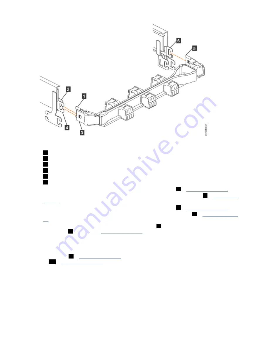
Figure 43. Connectors for the upper cable management arm
1
Inner connector on the upper CMA
2
Connector base on inner rail member
3
Outer connector on the upper CMA
4
Connector base on outer rail member
5
Support rail connector on the upper CMA
6
Connector base on outer rail member
1. Press the latch on the connector base on the upper CMA assembly (
5
2. Pull the connector to remove it from the connector base on the right support rail (
6
3. Press the latch on the outer connector of the upper CMA assembly (
3
4. Remove the outer connector from the inner member of the left support rail (
4
51).
5. Remove the inner connector of the upper CMA assembly (
1
) from the inner member of the left
support rail (
2
), as shown in Figure 43 on page 51.
Remove the lower CMA assembly
Note: The procedure for removing the lower CMA assembly is the same as the procedure to remove the
upper CMA assembly. However, the connector locations are reversed. For example, the connector base of
the upper CMA (
5
in Figure 43 on page 51) connects to the right rail. The connector base of the lower
CMA (
11
in Figure 44 on page 52) attaches to the left rail.
Chapter 2. Installing the system hardware 51
Summary of Contents for Storwize V5000 Gen2
Page 1: ...IBM Storwize V5000 Gen2 Quick Installation Guide IBM...
Page 5: ...Index 149 v...
Page 6: ...vi...
Page 156: ...130 Storwize V5000 Gen2 Quick Installation Guide...
Page 164: ...138 Storwize V5000 Gen2 Quick Installation Guide...
Page 166: ...140 Storwize V5000 Gen2 Quick Installation Guide...
Page 168: ...142 Storwize V5000 Gen2 Quick Installation Guide...
Page 177: ......
Page 178: ...IBM...


