124
RS/6000 SP and Clustered IBM
^
pSeries Systems Handbook
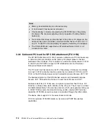
You must install a frame-to-frame, 10 m (33 ft.) electrical ground cable which is
supplied with the SP system when you order F/C 9122 and F/C 9123. This cable
is required in addition to the SP-attached server electrical ground. The
frame-to-frame ground maintains the SP system and the SP-attached server at
the same electrical potential.
The interconnection between the SP-attached server M/T 7017 and the SP
system, can be accomplished utilizing the IBM RS/6000 SP System Attachment
Adapter (F/C 8396) for the SP Switch connection.
If used, the adapter must be ordered as server feature code and it must be
installed in slot #10 of the server primary I/O drawer and slots #9 and #11 must
remain empty. Slot #9 must be left open to ensure the adapter has sufficient
bandwidth. Slot #11 must be left open to provide clearance for the switch adapter
heat sinks.
The SP Attachment Adapter uses an SP Switch cable to connect to an unused
switch port on the current SP configuration.
There are some SP-attached server placement limitations. Placement of the
SP-attached server is limited by the length of its following supplied cables:
1. The 10 m (33 ft.) frame-to-frame ground cable and RS/6000 SP System
Attachment adapter cable
2. The 15 m (49 ft.) RS-232 cables
3. The 15 m (49 ft.) BNC Ethernet cable
Approximately 3 m (10 ft.) of cable is needed for the vertical portion of the cable
runs. Thus, the SP-attached server must be no more than 7 m (23 ft.) from the
SP frame and no more than 12 m (40 ft.) from the control workstation.
Note: You must order one of the following cables which connect the adapter to
a valid switch port on the SP Switch:
10 m SP Switch/Switch or Switch/Node cable (F/C 9310)
20 m SP Switch to Switch cable (F/C 9320)
The cable must be ordered as part of the SP system.
Note: Refer to Chapter 10, “Clustering configurations” on page 285 for more
details about the SP-attached server environment.
Summary of Contents for RS/6000 SP
Page 2: ......
Page 6: ...iv RS 6000 SP and Clustered IBM pSeries Systems Handbook...
Page 16: ...xiv RS 6000 SP and Clustered IBM pSeries Systems Handbook...
Page 48: ...24 RS 6000 SP and Clustered IBM pSeries Systems Handbook...
Page 100: ...76 RS 6000 SP and Clustered IBM pSeries Systems Handbook...
Page 182: ...158 RS 6000 SP and Clustered IBM pSeries Systems Handbook...
Page 218: ...194 RS 6000 SP and Clustered IBM pSeries Systems Handbook...
Page 284: ...260 RS 6000 SP and Clustered IBM pSeries Systems Handbook...
Page 388: ...364 RS 6000 SP and Clustered IBM pSeries Systems Handbook...
Page 436: ...412 RS 6000 SP and Clustered IBM pSeries Systems Handbook...
Page 477: ...0 1 spine 0 1 0 169 53 89 pages RS 6000 SP and Clustered IBM pSeries Systems Handbook...
Page 478: ......
Page 479: ......

