background image

3.

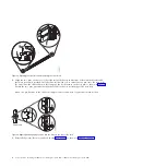
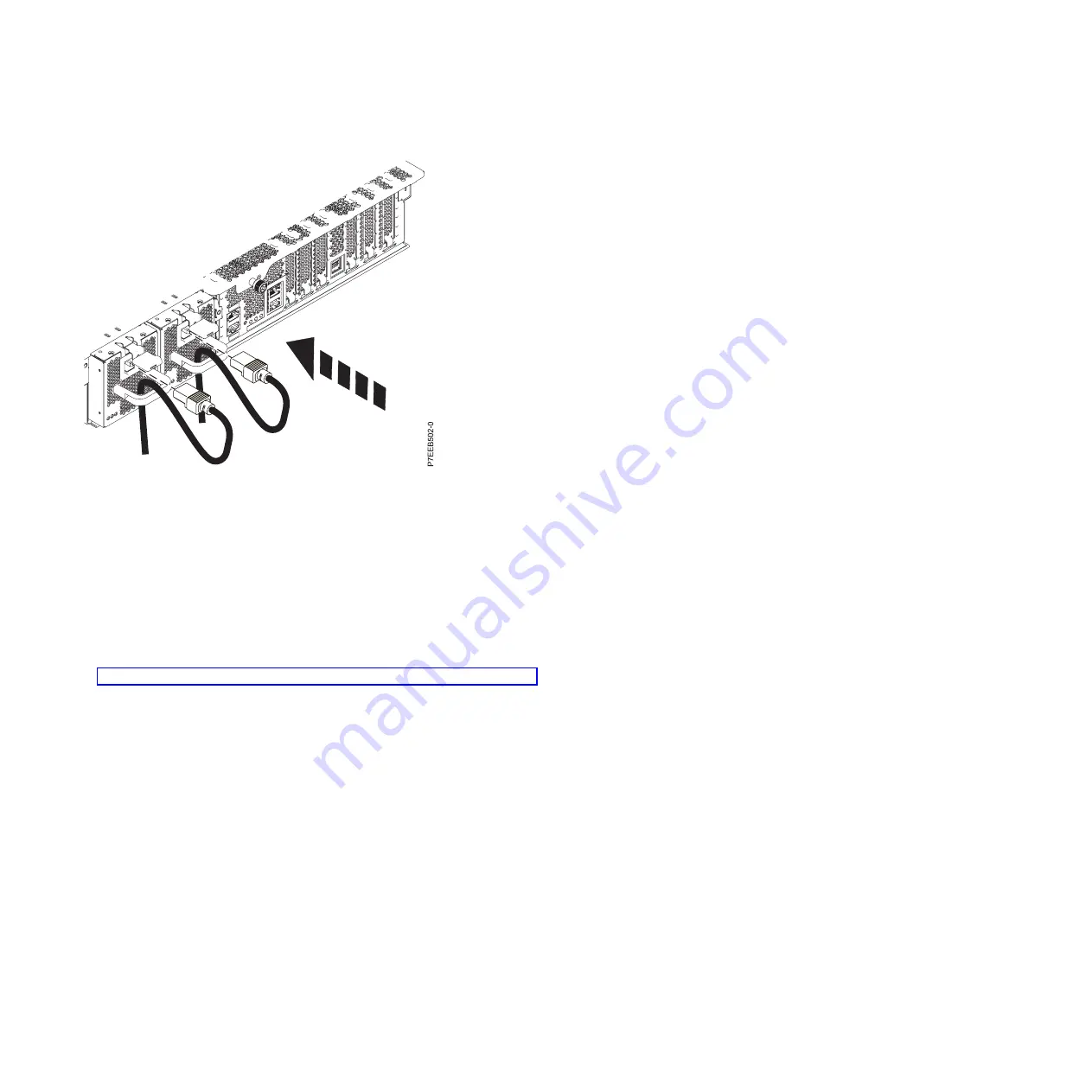
Plug the power cord into the power supply.

Note:

This system is equipped with two power supplies. If you want to configure the system with

redundant power supplies, you must connect each power cable to its own power source.

4.

Plug the system power cords and the power cords for any other attached devices into the alternating
current (ac) power source.

Note:

Confirm that the system is in standby mode. The green power status indicator on the front

control panel is flashing slowly, and the dc out indicator lights on the power supplies are flashing. If
neither indicator is flashing, check the power cord connections. For detailed information, see
“Common system attention LEDs and system reference codes” on page 31.

5.

If your system uses a power distribution unit (PDU), complete the following steps:

a.

Connect the system power cords from the server and I/O drawers to the PDU with an IEC 320
type receptacle.

b.

Attach the PDU input power cord and plug it into the alternating current (ac) power source.

Figure 21. Power cord attachment and routing

20

Power Systems: Installing the IBM Power 710 Express (8231-E1C) or IBM Power 730 Express (8231-E2C)

Summary of Contents for POWER 730

Page 1: ...Power Systems Installing the IBM Power 710 Express 8231 E1C or IBM Power 730 Express 8231 E2C GI11 9861 03...

Page 2: ......

Page 3: ...Power Systems Installing the IBM Power 710 Express 8231 E1C or IBM Power 730 Express 8231 E2C GI11 9861 03...

Page 4: ...Notices manual G229 9054 and the IBM Environmental Notices and User Guide Z125 5823 This edition applies to IBM Power Systems servers that contain the POWER7 processor and to all associated models Cop...

Page 5: ...Manager 17 Cabling the server with keyboard video and mouse 18 Connecting the power cables to the system 19 Completing the server setup 21 Completing the server setup by using Hardware Management Cons...

Page 6: ...iv Power Systems Installing the IBM Power 710 Express 8231 E1C or IBM Power 730 Express 8231 E2C...

Page 7: ...ct The documentation contains the safety information in your national language with references to the U S English source Before using a U S English publication to install operate or service this produ...

Page 8: ...ed to this product to properly wired outlets v When possible use one hand only to connect or disconnect signal cables v Never turn on any equipment when there is evidence of fire water or structural d...

Page 9: ...e customer to ensure that the outlet is correctly wired and grounded to prevent an electrical shock CAUTION v Do not install a unit in a rack where the internal rack ambient temperatures will exceed t...

Page 10: ...of the loaded rack cabinet Refer to the documentation that comes with your rack cabinet for the weight of a loaded rack cabinet v Verify that all door openings are at least 760 x 230 mm 30 x 80 in v...

Page 11: ...This product might contain one or more of the following devices CD ROM drive DVD ROM drive DVD RAM drive or laser module which are Class 1 laser products Note the following information v Do not remove...

Page 12: ...for NEBS Network Equipment Building System GR 1089 CORE The following comments apply to the IBM servers that have been designated as conforming to NEBS Network Equipment Building System GR 1089 CORE...

Page 13: ...allation v Philips screwdriver v Flat head screwdriver v Rack with two units of space If you do not have a rack installed see Installing the rack http publib boulder ibm com infocenter systems scope h...

Page 14: ...server into a rack by using the slide rail and cable management arm options To install the server into a rack complete the following tasks 1 Installing the server into a rack on page 3 2 Cabling the...

Page 15: ...ces http publib boulder ibm com infocenter systems scope hw topic p7hbf racksafety htm 2 Plan where to place the units Place the larger and heavier units in the lower part of the rack This system unit...

Page 16: ...om EIA unit that your system will use Make a note of the EIA location Use tape a marker or a pencil to mark the bottom hole of this EIA unit as A as shown in Figure 2 on page 5 Mark the rack so that t...

Page 17: ...8231 E1C or 8231 E2C mounting hardware to the rack You might need to attach the mounting hardware to the rack Use the procedure in this section to perform this task This section also includes illustr...

Page 18: ...sure the two pins protrude through the rack holes before proceeding to the next step Note The pin fixtures of the slide rails support either round hole or square hole rack models 4 Reinstall the screw...

Page 19: ...ge the hook feature on the middle pin as shown in Figure 6 7 While pulling the slide rail forward ensure that all three pins protrude through the rack holes then push the front latch 2 all the way in...

Page 20: ...o place Carefully lift the server and tilt it into position over the slide rails so that the rear nail heads 2 on the server line up with the rear slots 3 on the slide rails Slide the server down unti...

Page 21: ...iscard c Push the power supplies back into the system ensuring that they are fully seated and latched 5 Continue with Installing the cable management arm Installing the cable management arm You might...

Page 22: ...right side Connect one end of the support arm A to the right slide rail 1 so that you can swing the other end of the support arm 2 toward the left side of the rack as shown in Figure 12 2 Locate the h...

Page 23: ...2 as shown in Figure 14 4 Slide the extension bracket E into the right slide rail 1 Push the bracket into the slide rail until the spring loaded latch snaps into place as shown in Figure 15 on page 1...

Page 24: ...ment arm tab 2 into the slot on the mounting bracket C Push the tab until it snaps into place Pull out the other cable management arm pin 3 and then slide that cable management arm tab into the extens...

Page 25: ...bles as the cable management arm moves 9 Slide the server into the rack until it snaps into place Connecting the expansion units disk drives and PCI adapters Use this information to learn about connec...

Page 26: ...ecting PCI adapters PCI adapter placement http publib boulder ibm com infocenter systems scope hw topic p7hak p8231pcianddiv htm 14 Power Systems Installing the IBM Power 710 Express 8231 E1C or IBM P...

Page 27: ...itor and USB cables equipped with KVM Cabling the server with keyboard video and mouse on page 18 Cabling the server with an ASCII terminal If you are not creating logical partitions you can use an AS...

Page 28: ...nue with Completing the server setup without using a management console on page 23 Cabling the server to the Hardware Management Console The Hardware Management Console HMC controls managed systems in...

Page 29: ...tions see Completing the server setup by using Hardware Management Console on page 21 Cabling the server and accessing the Integrated Virtualization Manager When you install the Virtual I O Server VIO...

Page 30: ...ll Boot Device and press Enter c Select CD DVD and press Enter d Select the media type that corresponds to the optical device and press Enter e Select the device number that corresponds to the optical...

Page 31: ...o the system complete the following steps 1 Remove the power supply shipping bracket if present as shown in Figure 20 Ensure that the power supplies have been reseated 2 While facing the rear of the s...

Page 32: ...hing slowly and the dc out indicator lights on the power supplies are flashing If neither indicator is flashing check the power cord connections For detailed information see Common system attention LE...

Page 33: ...tor lights on the power supplies are flashing If none of the indicators are flashing check the power cord connections 3 Power on the managed system 4 Install and update an operating system if it is no...

Page 34: ...nt release 7 Power on your managed system by using the correct Power On Parameters To power on your managed system by using the HMC complete the following steps a View your managed system s properties...

Page 35: ...ng level of server firmware in the upper right corner under the copyright statement c Update the time of day In the navigation area expand System Configuration d Click Time of Day The right pane displ...

Page 36: ...24 Power Systems Installing the IBM Power 710 Express 8231 E1C or IBM Power 730 Express 8231 E2C...

Page 37: ...ation see Prerequisite for installing the 8231 E1C and 8231 E2C on page 1 Perform the inventory For more information see Before you begin on page 1 Verify that you have a rack You must first have a ra...

Page 38: ...disk drives and PCI adapters v Do not power on your system You will be instructed to power on the system when you set up the console For more information see Connecting the expansion units disk drives...

Page 39: ...nd PCI adapters if applicable Notes v Consult your project manager or read the system plans before moving or installing any disk drives and PCI adapters v Do not power on your system You will be instr...

Page 40: ...ver for setup purposes only After setup you can use any PC or notebook on your network that is running Netscape 9 0 0 4 Microsoft Internet Explorer 7 0 Opera 9 24 or Mozilla Firefox 2 0 0 11 as your A...

Page 41: ...pears enter admin for the user ID and password 8 Change the default password when prompted 9 Choose from the following options v If you do not plan to connect your PC or notebook to your network this...

Page 42: ...TCP IPv4 and then click Properties Attention Record the current settings before making any changes Use this information to restore these settings if you disconnect the PC or notebook after setting up...

Page 43: ...ower is not being supplied to one of the power supplies but power is being supplied to the second power supply and the system is powered on Off Off Off Off Power is not being supplied to either power...

Page 44: ...ample for concurrent maintenance symmetric multiprocessing cables label the cables appropriately and note the sequence order v To facilitate cable routing install cables in the following order 1 Syste...

Page 45: ...available for each point to point connection v If cables have to be routed across the rear of a drawer leave enough slack to reduce the tension on the cables for maintenance of the drawer v When routi...

Page 46: ...Related information POWER7 770 780 Cabling guide Figure 23 Cable bend radius 34 Power Systems Installing the IBM Power 710 Express 8231 E1C or IBM Power 730 Express 8231 E2C...

Page 47: ...or changes in the product s and or the program s described in this publication at any time without notice Any references in this information to websites not owned by the manufacturer are provided for...

Page 48: ...operations Users should periodically check the manufacturer s support websites for updated information and fixes applicable to the system and related software Homologation statement This product may...

Page 49: ...2 this device must accept any interference received including interference that may cause undesired operation Industry Canada Compliance Statement This Class A digital apparatus complies with Canadia...

Page 50: ...n JEITA Confirmed Harmonics Guideline products less than or equal to 20 A per phase Japanese Electronics and Information Technology Industries Association JEITA Confirmed Harmonics Guideline with Modi...

Page 51: ...Vertr glichkeit Dieses Produkt entspricht den Schutzanforderungen der EU Richtlinie 2004 108 EG zur Angleichung der Rechtsvorschriften ber die elektromagnetische Vertr glichkeit in den EU Mitgliedsst...

Page 52: ...f r die Einhaltung der EMV Vorschriften ist der Hersteller International Business Machines Corp New Orchard Road Armonk New York 10504 Tel 914 499 1900 Der verantwortliche Ansprechpartner des Herstel...

Page 53: ...complies with Part 15 of the FCC rules Operation is subject to the following two conditions 1 this device may not cause harmful interference and 2 this device must accept any interference received in...

Page 54: ...ies Association JEITA Confirmed Harmonics Guideline with Modifications products greater than 20 A per phase IBM Taiwan Contact Information Electromagnetic Interference EMI Statement Korea Germany Comp...

Page 55: ...r International Business Machines Corp New Orchard Road Armonk New York 10504 Tel 914 499 1900 Der verantwortliche Ansprechpartner des Herstellers in der EU ist IBM Deutschland GmbH Technical Regulati...

Page 56: ...in full compliance with all applicable laws and regulations including all United States export laws and regulations IBM MAKES NO GUARANTEE ABOUT THE CONTENT OF THESE PUBLICATIONS THE PUBLICATIONS ARE...

Page 57: ......

Page 58: ...Part Number 00L5066 Printed in USA GI11 9861 03 1P P N 00L5066...

Reviews: