Note:
The procedure for installing the cable-management arm involves the assembly of the following
parts:
A
Support arm
B
Cable-management stop bracket
C
Mounting bracket
D
Cable-management arm
E
Extension bracket
Figure 11 shows the parts of the cable-management arm in relative position to each other before their
assembly.
1.
The cable-management arm must be installed on the right side of the server, when you are facing it
from the rear. The following figure shows it being installed on the right side. Connect one end of the
support arm
(A)
to the right slide rail
(1)
so that you can swing the other end of the support arm
(2)
toward the left side of the rack, as shown in Figure 12.
2.
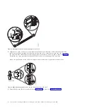
Locate the hole at the bottom inside corner of the L-shaped cable-management stop bracket
(B)
.
Position the unattached end of the support arm so that the locking tab on the underside of its tip
aligns with the bracket hole. Insert the tab into the hole
(1)
and turn the bracket
(2)
to secure it to the
Figure 11. Relative positions of cable-management arm parts before assembly
Figure 12. Connecting the support arm
10
Power Systems: Installing the IBM Power 710 Express (8231-E1C) or IBM Power 730 Express (8231-E2C)
Summary of Contents for POWER 730
Page 2: ......
Page 57: ......
Page 58: ...Part Number 00L5066 Printed in USA GI11 9861 03 1P P N 00L5066...


