background image

Unloading the Stacker

Do this task when you need to remove printed forms from the stacker or when

you see the following message:

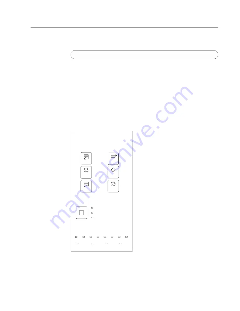
STACKER FULL 0796

Some controls you need to use to accomplish this task are available only on the

stacker control panel, and some are available on the Display Touch Screen window.

1.

If you need to stop the printer, SELECT the Stop pushbutton on the Display

Touch Screen window.

2.

If you need to remove all the current forms from the forms path, separate the

forms at a perforation below the transfer station. Ensure that the end-of-forms

sensors are uncovered. Open the static brush so the forms fall back into the

box or input area.

3.

If you need to move forms to the stacker, SELECT the NPRO pushbutton on

the Display Touch Screen window.

If

END OF FORMS

appears, repeat this step again.

4.

On the stacker control panel, press the stacker table Down switch and wait for

the stacker table to stop moving.

HC6OG026

A 16-22 lbs(51-71kg)60-82g

B 23-42 lbs(72-135kg)83-157g

C Plastic

7

0

11

1/2

9

1/3

13

2/3

8

12

10

14

Forms Select

Forms Length

Table

Forms
Feed

STOP

Stop

READY

Up

Down

Forward

Chapter 6. Operator Responsibilities

169

Summary of Contents for INFO PRINT 3000

Page 1: ...InfoPrint 3000 Operator s Guide S544 5564 01 IBM ...

Page 2: ......

Page 3: ...InfoPrint 3000 Operator s Guide S544 5564 01 IBM ...

Page 4: ... IBM representative or to the IBM branch office serving your locality If you request publications from the address given below your order will be delayed because publications are not stocked there A Reader s Comment Form is provided at the back of this publication If the form has been removed comments can be sent by fax to 1 800 524 1519 by E mail to print_pubs us ibm com or by mail to IBM Printin...

Page 5: ...r programs if the program s license terms permit a transfer You must at the same time destroy all other copies of the documentation You are responsible for payment of any taxes including personal property taxes resulting from this authorization THERE ARE NO WARRANTIES EXPRESS OR IMPLIED INCLUDING THE WARRANTIES OF MERCHANTABILITY AND FITNESS FOR A PARTICULAR PURPOSE Some jurisdictions do not allow...

Page 6: ...iv InfoPrint 3000 Operator s Guide ...

Page 7: ...eveloper Area 20 Forms Input and Transfer Station Area 22 Printer Control Panel 23 Transfer Station Control Lever and Tractor Control Levers 25 Puller Control Lever 26 Fuser Entry Area 26 Stacker Area 27 Stacker Control Panel 28 Forms Length and Width Controls 30 Stacker Height Control 31 Rear Service Area 32 Chapter 4 Using the Display Touch Screen 33 Using the Display Touch Screen in Duplex and ...

Page 8: ... the Buffer Flipper Unit 167 Straight Line Configuration 167 Left Angle Configuration 168 Unloading the Stacker 169 Switching Printer Modes Dual Simplex Duplex 172 Switching from Duplex to Dual Simplex Mode 172 Switching from Dual Simplex to Duplex Mode 172 Switching Print Resolution 174 Chapter 7 Ordering and Replacing Supplies 175 Supplies 176 IBM Supplies Worksheet 176 Ordering Supplies 177 Mai...

Page 9: ...ppendix A Valid Form Lengths in Inches 291 Appendix B Physical System Layouts 293 Simplex Models 293 Duplex Models 294 Glossary 297 Index 305 Readers Comments We d Like to Hear from You 311 Contents vii ...

Page 10: ...viii InfoPrint 3000 Operator s Guide ...

Page 11: ...t Registration 71 22 Sample Field Adjusted Registration 72 23 Options Pull Down Menu 80 24 Stacker Height Control 117 25 Reprint Path Length 121 26 Duplex Mode Reprint Path Length 127 27 Reestablishing Forms Alignment 130 28 Printer Usage Sheet 147 29 Traces Window 148 30 Setup Window for Thread Align Forms 152 31 Main Thread Align Forms Window 154 32 Inline Configuration 167 33 Left Angle Configu...

Page 12: ...x InfoPrint 3000 Operator s Guide ...

Page 13: ...plex Mode 131 15 IBM Supplies Worksheet 177 16 Printer Configuration Items 221 17 Parallel Channel Attachment Items 232 18 ESCON Channel Attachment Items 234 19 Token Ring TCP IP Attachment Items 235 20 Ethernet TCP IP Attachment Items 237 21 FDDI TCP IP Attachment Items 239 22 Preprocessing Postprocessing Interface Options 241 23 Pre Postprocessor Device Configuration Items 243 24 Configuration W...

Page 14: ...xii InfoPrint 3000 Operator s Guide ...

Page 15: ... Date of Installation The date on your receipt is the Date of Installation unless IBM or your reseller informs you otherwise During the warranty period IBM or your reseller will provide warranty service under the type of service designated for the Machine and will manage and install engineering changes that apply to the Machine IBM or your reseller will specify the type of service For a feature co...

Page 16: ...your reseller of changes in a Machine s location and d For a Machine with exchange service remove all features parts options alterations and attachments not under warranty service Also the Machine must be free of any legal obligations or restrictions that prevent its exchange and 3 Be responsible for loss of or damage to a Machine in transit when you are responsible for the transportation charges ...

Page 17: ...harge for the Machine that is the subject of the claim Under no circumstances is IBM liable for any of the following 1 Third party claims against you for losses or damages other than those under the first item listed above 2 Loss of or damage to your records or data or 3 Economic consequential damages including lost profits or savings or incidental damages even if IBM is informed of their possibil...

Page 18: ...xvi InfoPrint 3000 Operator s Guide ...

Page 19: ...ons IBM Corporation Purchase NY 10577 U S A For online versions of this book we authorize you to v Copy modify and print the documentation contained on the media for use within your enterprise provided you reproduce the copyright notice all warning statements and other required statements on each copy or partial copy v Transfer the original unaltered copy of the documentation when you transfer the...

Page 20: ... generates uses and can radiate radio frequency energy and if not installed and used in accordance with the instruction manual may cause harmful interference to radio communications Operation of this equipment in a residential area is likely to cause harmful interference in which case the user will be required to correct the interference at his own expense Properly shielded and grounded cables and...

Page 21: ...nicht ausreichend entstört sind nur mit besonderer Genehmigung des Bundesminesters für Post und Telekommunikation oder des Bundesamtes für Post und Telekommunikation betrieben werden Die Genehmigung wird erteilt wenn keine elektromagnetischen Störungen zu erwarten sind Auszug aus dem EMVG vom 9 Nov 92 Para 3 Abs 4 European Community EC Conformity Statement This product is in conformity with the pr...

Page 22: ...s aware of hazards that can cause minor or moderate personal injuries such as cuts or burns The following notices are examples of the kinds of caution notices that can appear in an Operator s Guide CAUTION 70 The oiler belt oiler wick roll and their environments are areas Be very careful when working in these areas high temperature CAUT0100 xx InfoPrint 3000 Operator s Guide ...

Page 23: ...Danger Notices Danger notices make users aware of hazards that can cause serious injury or death The following are examples of danger notices Notices xxi ...

Page 24: ...Safety Notices xxii InfoPrint 3000 Operator s Guide ...

Page 25: ...g safeguards to ensure that laser radiation is inaccessible or within Class 1 limits There are various tool operated machine covers that should be moved removed or replaced only by trained service personnel There are no operator controls or adjustments associated with the laser No operator maintenance is required to keep the product in compliance as a Class 1 Laser Product No adjustments that affe...

Page 26: ...icing companies and customers who are not using IBM service are encouraged to use those procedures Postage is paid by IBM Customers using IBM service should have their drums returned by the service representative The photoconductor drum may be subject to special disposal requirements in your area Customers should consult local disposal regulations if they elect not to use the return procedure offe...

Page 27: ...perator Responsibilities on page 55 contains step by step instructions for performing operator tasks v Chapter 7 Ordering and Replacing Supplies on page 175 contains step by step instructions for ordering and replacing supplies for the printer v Chapter 8 Configuring the System on page 217 contains information and step by step instructions for configuring the printer the host attachments and the p...

Page 28: ...essages on page 271 Terminology For definitions of terms used in this publication as well as other publications in the printer library see the Glossary on page 297 Notation Conventions The following notation conventions are used throughout this publication v Words that appear in messages on a Display Touch Screen window are shown in COMPUTER print For example CHANGE DEVELOPER MIX v The words SELEC...

Page 29: ...tion Common Control Unit G544 3895 which contains technical information about the host to printer data stream and exception reporting v InfoPrint 3000 Maintenance Information Manuals IBM Part Number 24L4856 which contain technical information about maintaining and repairing the printers Related Publications An extensive listing of available publications is included in Advanced Function Presentatio...

Page 30: ...xxviii InfoPrint 3000 Operator s Guide ...

Page 31: ...cription and Value Option for PQE Boldness in Table 25 on page 258 Table 24 on page 251 and Table 16 on page 221 were updated v One of two forms identification worksheets in Chapter 8 was deleted v Miscellaneous changes were made to Table 15 on page 177 v Deletions were made in Customer Replaceable Supply Items on page 177 v The Toner Yield Calculations appendix was deleted Copyright IBM Corp 1998...

Page 32: ...xxx InfoPrint 3000 Operator s Guide ...

Page 33: ...r reviews the characteristics of the IBM InfoPrint 3000 including the following models v ES1 v ED1 ED2 System Characteristics Table 1 on page 2 summarizes the specifications for the various printers in the InfoPrint 3000 family Copyright IBM Corp 1998 1 ...

Page 34: ...rection 7 The maximum paper weight for duplex printers running in simplex mode should be 160 g m2 42 lb 8 Maximum form length is 356 0 3 mm 14 0 013 in when used with the on board stacker 9 Maximum form length is 711 0 3 mm 28 0 013 in when used with preprocessing and postprocessing devices Note The InfoPrint 3000 operates in simplex and duplex mode depending on the model selected Model ES1 operat...

Page 35: ... and electronic overlays can be placed at any defined point on the page areas on which the printers can print System Components Model ED1 This model includes Printer engine Printer Utility Module PUM This unit includes Operator alert assembly Power control panel System interconnection electronics Preprocessing postprocessing device interfaces Models ES1 and ED2 These models include Printer engine ...

Page 36: ... prints the other side of the form This publication calls the first printer Printer 1 and the second printer Printer 2 Allowable printer system configurations are inline see Inline Configuration for Duplex on page 6 or a left 90 angle see Left Angle Configuration for Duplex on page 7 Only a Buffer Flipper Unit may be between Printer 1 and Printer 2 but no preprocessing or postprocessing devices Th...

Page 37: ... configured as dual simplex and one of the printers is inoperable the remaining printer can run independently so long as power and connection to the control unit are maintained Alternatively forms can remain threaded continuously through both printers in a duplex physical configuration but with printing occurring in simplex mode Printing occurs on only one printer while the other printer processes...

Page 38: ...nal preprocessing device 2 Printer Utility Module PUM attached to Printer 1 3 Printer 1 4 Buffer Flipper Unit 5 AFCCU attached to Printer 2 6 Printer 2 7 Optional postprocessing device HC6I0010 1 2 3 4 5 6 7 6 InfoPrint 3000 Operator s Guide ...

Page 39: ... Optional preprocessing device 2 Printer Utility Module PUM attached to Printer 1 3 Printer 1 4 Buffer Flipper Unit 5 AFCCU attached to Printer 2 6 Printer 2 7 Optional postprocessing device HC6I0008 1 2 3 4 5 6 7 Chapter 1 Introduction 7 ...

Page 40: ...er Utility Module PUM attached to Printer 1 3 Printer 1 4 Optional preprocessing device for Printer 2 5 Optional postprocessing device for Printer 1 6 AFCCU attached to Printer 2 7 Printer 2 8 Optional postprocessing device for Printer 2 HC6I0009 1 2 3 4 5 6 7 8 8 InfoPrint 3000 Operator s Guide ...

Page 41: ...ify side 2 printing When loading new forms after a power on or restart and after any machine detected errors Thread Align Forms on page 152 Also see Verification Marks on page 224 Change mode from duplex to dual simplex or dual simplex to duplex As necessary Change the Printer Mode using Switching Printer Modes Dual Simplex Duplex on page 172 Empty stacker As necessary Unloading the Stacker on pag...

Page 42: ... representative Changing the Language of Messages on page 218 Configuring the Printer on page 219 Configuring the Host Attachments on page 229 Configuring Preprocessing Postprocessing Devices Interfaces on page 241 Clean the oiler belt Once each week Cleaning the Oiler Belt on page 86 Check the absorbent pad in the oil pan if they are installed Once each week Checking the Absorbent Pad in the Oil ...

Page 43: ...e Ready pushbutton on the Display Touch Screen main window has been selected When the printer is operating normally the following happens v In simplex mode forms move 1 From the preprocessor or forms input area 2 Through the transfer station and fuser 3 Into the stacker or postprocessor area v In duplex mode forms continue 1 Past the stacker area of Printer 1 through the Buffer Flipper Unit 2 Into...

Page 44: ...at the printer needs basic service that involves handling forms or checking on mechanical conditions such as an open gate You must handle all messages of this type before printing can continue v Printer Error messages indicate that the printer or the control unit has a hardware problem such as a forms jam or a component failure Processing stops so that you can attempt to correct the problem or if ...

Page 45: ...problem The service representative always needs the following information v The number and exact text of each message listed in the order of their appearance on the Display Touch Screen v A description of the forms that are used size weight adhesive labels and preprinted forms Also the following optional information may be useful v A description of the application that was running v A description ...

Page 46: ...14 InfoPrint 3000 Operator s Guide ...

Page 47: ...ol panel v Transfer station control lever v Puller control lever v Fuser entry area v Stacker area stacker control panel and forms length and width controls v Rear service area Forms and the Forms Path Form refers to pages on which the printer can print Forms can be blank paper preprinted paper adhesive labels cards or any other printable material that meets the required specifications Paper is a ...

Page 48: ...g differences when you use a printer for duplex or simplex printing If the printer is Printer 1 in the configuration the stacker is disabled The forms exit the printer to the left from the Output Stacker Area 4 directly to the Buffer Flipper Unit If a preprocessing device is installed the forms enter from the right under the printer to the urge unit and then move up through the Forms Input area 6 ...

Page 49: ...assembly are in the control unit area 1 Operator Alert Assembly 2 Display Touch Screen 3 Power Control Panel 4 AFCCU Frame in a simplex printer or in Printer 2 of a duplex configuration or Printer Utility Module PUM Frame in Printer 1 5 Printer Engine Frame Chapter 3 Functional Areas 17 ...

Page 50: ... Chapter 4 Using the Display Touch Screen on page 33 describes it in detail Power Control Panel On Printer 1 of a duplex system the Power Control Panel provides power control for the Printer Utility Module PUM frame and the printer engine On Printer 2 of a duplex system and on a simplex printer the Power Control Panel provides direct power control for the AFCCU frame and the printer engine The Pow...

Page 51: ...on and off by the Control Unit Power On and Control Unit Power Off If In Local switches on this panel Control Unit Power On Switch Powers on the AFCCU frame or the PUM frame when the Control Unit Local Remote switch is set to Local Printer Power On Switch Powers on the printer when the Printer Local Remote switch is set to Local Control Unit Power Off If In Local Switch Powers off the AFCCU when t...

Page 52: ...ter Control Panel You add developer mix through the developer mix inlet 2 The developer drain lever 3 which is marked with a B label opens and closes the developer drain The developer run pushbutton 4 which is marked with an A label causes new developer mix to move from the developer mix inlet into the developer FORM S WIDT H 18 17 16 15 14 13 12 11 10 9 8 HC6OG014 1 2 4 3 A B 20 InfoPrint 3000 Op...

Page 53: ...o the developer Developer Drain Lever 3 Starts the developer mix drain process to move developer mix from the developer into an external container for disposal Developer Run Pushbutton 4 Starts the developer mix load process to move developer mix from the developer inlet into the developer also aids in removing used developer mix from the developer Chapter 3 Functional Areas 21 ...

Page 54: ... forms input area In the transfer station area print images are transferred from the photoconductor drum to the forms that are traveling through the printer Printer Control Panel on page 23 describes the printer control panel in detail 1 Transfer station 2 Developer area 3 Printer control panel 4 Forms input area 5 Static brushes 6 Tension arm 22 InfoPrint 3000 Operator s Guide ...

Page 55: ... 4 Printer Control Panel Using This Control Does This Darker Contrast Control Key Adjusts print contrast from lighter 1 to darker 7 The current setting is marked by an LED Lighter Contrast Control Key Adjusts print contrast from darker 7 to lighter 1 The current setting is marked by an LED Chapter 3 Functional Areas 23 ...

Page 56: ...If the indicator displays the opposite fold direction or no fold direction press the appropriate key to change the setting Note This control is used only for fan fold forms that are stacked at the printer stacker If the control is not set correctly the stacker jams Forms Feed Forward Moves the forms toward the transfer station and stacker area Forms in the forms path between the transfer station a...

Page 57: ...transfer station in a clockwise direction You then move the lever to the left and press down on the transfer station to latch it in place During printing the transfer station should be firmly latched in the closed position Tractor Control Levers 2 Allow you to change the distance between the front and rear tractors When you move the levers to the left the tractors are free to move forward or backw...

Page 58: ...fuser area The lever is spring loaded so pressure returns to the scuff and backup rollers when you release the puller lever Fuser Entry Area After they receive print images the forms pass through the fuser entry area toward the fuser In the fuser area heat and pressure from the fuser heat roll bond the print images onto the forms 26 InfoPrint 3000 Operator s Guide ...

Page 59: ...ote Roll feed forms do not use the stacker area They require a postprocessor The pendulum is inside the stacker area above the stacker table The swinging of the pendulum helps the forms to refold correctly 1 Forms length and width controls 2 Stacker end cover 3 Stacker table 4 Finger belts 5 Stacker gate open 6 Stacker control panel HC6OG045 1 6 2 3 4 5 FO RM S WI DT H 18 17 16 15 14 13 12 11 10 9...

Page 60: ...inters Ready when the printing system is in duplex mode or makes the individual printer Ready when the system is in dual simplex mode If pages are waiting to be printed and the system or printer is online to the host printing begins Finishes the page that is currently being printed and makes the printing system both printers Not Ready in duplex mode or the individual printer Not Ready in simplex m...

Page 61: ...s the fusing temperature and the amount of fuser oil used during printing The current selection is indicated by an LED Not setting Forms Select correctly can reduce print quality v The A setting is for 16 22 lbs 60 82 g m 2 weight forms It should not be used for heavier weight forms v The B setting is for 23 42 lbs 83 157 g m2 weight forms It uses more fuser oil than setting A and should not be us...

Page 62: ...ecreases the stacker length setting You can set the forms length from 7 to 14 inches The length increases or decreases in increments of one third and one half inch You turn the knob clockwise to increase the forms length You turn the knob counterclockwise to decrease the forms length The length you set with the FORMS LENGTH knob is indicated by the LEDs on the Stacker Control Panel 30 InfoPrint 30...

Page 63: ...e height of the output stack While this reduces the weight of the output stack it also required you to empty the stacker more often For more information on using this control see Adjusting the Stacker Table Height on page 117 Note Use this control only for fan fold forms not for roll feed forms HC6OG077 300 250 COUN TER COUN TER 5 15 10 20 25 Figure 3 Stacker Height Control Chapter 3 Functional Ar...

Page 64: ...frame Note that the preprocessing postprocessing device interface cable connection area is the same on the AFCCU frame of the following v A simplex printer v Printer 2 of a duplex or dual simplex configuration v Or the PUM frame on Printer 1 1 Fuser oil reservoir 2 Usage meter 3 Toner collector 4 Fine filter 5 Pre Postprocessor device cable connection area behind rear cover 6 Operator alert assemb...

Page 65: ...ail The windows on your Display Touch Screen have a title bar at the top that is not shown in this book Using the Display Touch Screen in Duplex and Dual Simplex Modes In duplex mode the two printers work as one logical printer and are controlled from a single Display Touch Screen In dual simplex mode each physical printer works independently of the other The monitor has two logical Display Touch ...

Page 66: ...ual printer Ready when the system is in dual simplex mode If pages are waiting to be printed and the system or printer is online to the host printing begins Stop finishes the page that is currently printing It then makes the complete system both printers Not Ready in duplex mode or the individual printer Not Ready in simplex mode Check Reset Informs the system that the error has been corrected and...

Page 67: ... you see when you select the Printer Status procedure from the Operate pull down menu Figure 10 on page 44 shows all pull down menu procedures It also shows which pull down menu you use to access each procedure Shading indicates the user authorization level that is required of each procedure Chapter 5 Task Summary on page 43 summarizes all of the functions available from the pull down menus Keyboa...

Page 68: ...r one character space to the left Right Moves the cursor one character space to the right Backspace Erases an existing character to the left of the cursor Caps Alphanumeric Keyboard Only Acts as a switch to change keyboard entries from lowercase to uppercase or uppercase to lowercase Shift Alphanumeric Keyboard Only Affects only the next character you enter by changing the case upper or lower set ...

Page 69: ...ar action which occurs immediately An ellipsis that follows a pushbutton name means that selecting the pushbutton causes a another procedure window or a pop up window to appear Selectable Field A selectable field on a procedure window or a pop up window displays the current setting of an item that you can change To change the setting SELECT the field A pop up window appears containing one of the f...

Page 70: ...w additional unseen information in the box Inactive Items All pushbutton text selection list items and pull down menu procedures appear regardless of whether they are currently selectable Not all items are available on all printer models Items that you cannot select are grayed out which means the text is faint but readable For example when a printer is in the Ready state the Check Reset pushbutton...

Page 71: ...ver only five procedures can appear on the Display Touch Screen at one time To switch back and forth between the procedures on the Display Touch Screen select the title bar of the procedure you want If there are more than five procedures that are active you can still use the procedures that have been pushed off the display Do this by selecting the Switch to option from the System Menu pull down me...

Page 72: ... there is no user interaction or error condition on the operator console for a period of time the console goes blank Only a floating logo screen saver appears To return to the normal display simply touch the screen The screen saver timeout period length of time without user interaction before the screen saver comes on is set under the Configure Printer procedure The timeout period ranges from 0 to...

Page 73: ...e field You can select any field with this three dimensional outline A pop up window a keyboard or a keypad window appears when you select a field that you can change A26O0027 This two dimensional outline signifies a field that you cannot change You cannot select any field with this two dimensional outline Text in the two dimensional box is for your information only A26O0018 This is the scroll bar...

Page 74: ...appears for you to make an entry A26O0021 This symbol appears within some field boxes It indicates that this field contains more choices than are currently displayed When you select this field a pop up window appears containing a selection list box with the additional choices A26O0022 Pushbutton or menu item text that is followed by an ellipsis indicates that when you select that item another wind...

Page 75: ...ailable from the printer pull down menus Figure 10 on page 44 shows all pull down menu procedures It also shows which pull down menu you use to access each procedure Shading indicates the user authorization level that is required of each procedure Copyright IBM Corp 1998 43 ...

Page 76: ...ts Print Attachment Configuration Adjust Print Remote Access Print Test Configure Pre Post Print Traces Save Traces Print Samples Configure Control Unit Trace Password Print Adjust Print Test Change Password Assign Form to Load Traces Change Language Clean Screen Calibrate Touch Screen Front Face Special Features A23O0142 Attachments Cancel Job Clear Buffers Thread Align Forms NPRO NPRO Page Shutd...

Page 77: ...ge 278 for more information Cancel Job Lets you cancel the job that is currently printing In simplex or dual simplex mode only the individual printer must be in a Not Ready state See Canceling a Job on page 78 for more information Clear Buffers Clears the print buffers You must make the printer Not Ready before you select Clear Buffers This procedure allows the host to use PSF Forward and Backward...

Page 78: ...es the system so that you can power off the control unit In duplex mode Shutdown affects the complete system In simplex or dual simplex mode Shutdown applies to just the printer for which the procedure was selected You can still use the other printer v Restart unloads and then reloads the control unit internal code This resets pointers counters and other controls In duplex mode the complete system...

Page 79: ...See Configuring the Host Attachments on page 229 for more information Configure Pre Post Lets you add delete or change the specifications of preprocessing or postprocessing device interfaces See Configuring Preprocessing Postprocessing Devices Interfaces on page 241 for more information Adjust Print Shifts the logical page on a form when you are using preprinted forms or other forms that require p...

Page 80: ...Network Management Protocol SNMP Remote Management Interface RMI and Modem See Configuring Remote Access on page 245 for more information 48 InfoPrint 3000 Operator s Guide ...

Page 81: ...t a trace to run start the trace stop the trace save a trace to diskette and print selected traces See Running Traces on page 148 for more information Print Samples Lets you print a variety of sample pages See Checking Print Quality on page 85 for more information Operate Configure Analyze Options Help Ready Check Reset NPRO Cancel Job Service Actions Print Samples HC6OG090 Traces Figure 13 Analyz...

Page 82: ...erson who is working on the printer It also allows you to change the user authorization password Access to higher user authorization levels is password protected See Changing the Password or Authorization Level on page 79 for more information Change Language Lets you change the language that is used for all text within Display Touch Screen windows See Changing the Language of Messages on page 218 ...

Page 83: ...that jobs that require a certain folding pattern are printed correctly See Checking for a Front Facing Page on page 81 for more information Special Features Lets you enable disable install and uninstall special features customer requested features that are also known as RPQs You can install special features from a diskette or from the printer hard disk drive You must both install and enable the fe...

Page 84: ...own Menu The Help pull down menu has only one choice General Help SELECTING General Help displays general information about the Display Touch Screen Figure 15 General Help Window 52 InfoPrint 3000 Operator s Guide ...

Page 85: ... information usually includes a summary of the procedure directions for performing the procedure and an explanation of each pushbutton in the procedure window For example selecting the Help pushbutton when you are defining forms causes the following window to appear Figure 16 Define Forms Help Window Chapter 5 Task Summary 53 ...

Page 86: ...54 InfoPrint 3000 Operator s Guide ...

Page 87: ...e Post Devices 118 Enabling Disabling Pre Post Interfaces 118 Using the Printer Stacker 119 Error and Jam Recovery 119 Adding Supplies 119 Nonprocess Runout NPRO 120 Recovering from a Forms Jam Simplex Operations 121 Jams Within the Printer Engine 122 Jam Recovery Procedures 123 Jams Between the Printer and a Postprocessing Device 126 Recovering from a Forms Jam Duplex Operations 127 Jams Within P...

Page 88: ... 7 Ordering and Replacing Supplies on page 175 Controlling the System Power The following figure shows a Power Control Panel Printer 1 in a duplex or dual simplex printing system has two sets of power controls One is for the Printer Utility Module PUM frame which is labeled Control Unit on the Power Control Panel The other is for the printer that is attached to the PUM frame Printer 2 in a duplex ...

Page 89: ... 2 AFCCU Frame Powering On the System You can switch power on for the complete system for duplex or simplex mode use You can also switch power on for only one printer and its associated control unit in simplex mode when one of the two system printers is not operable and needs repair In either mode and with the use of either printer you must switch the AFCCU power on How you switch power on for the...

Page 90: ...a three phase electrical outlet that is reserved for the printer 3 Inform the host system console operator that the system is ready to be powered on 4 Respond to any error or intervention messages that appear on the Display Touch Screen during the power on sequence At the completion of the power on sequence the Display Touch Screen displays a Printer Status window In duplex mode the Printer Status...

Page 91: ...outlet that is reserved for the printer 3 Press the AFCCU frame Control Unit Power On switch for any of the preceding combinations of elements listed 4 Respond to any error or intervention messages that appear on the Display Touch Screen during the power on sequence 5 At the completion of the power on sequence the Display Touch Screen displays a Printer Status window In duplex mode the Printer Sta...

Page 92: ... 5 The host system console operator switches power off to the system remotely In Local Controlled Mode 1 On the Display Touch Screen from the Operate pull down menu SELECT the Shutdown Restart procedure 2 On the Shutdown Restart window SELECT the Shutdown pushbutton In dual simplex mode on the Shutdown Restart window SELECT the Shutdown pushbutton for the other printer if desired Wait for a Shutdo...

Page 93: ... off power to the AFCCU regardless of whether a recovery action procedure instructed you to switch power off to the system or you are doing it on your own Shutting Down the System Note With a duplex configuration in duplex mode or with a simplex printer this procedure shuts down the complete system both printers in a duplex configuration In dual simplex mode this procedure shuts down only the targ...

Page 94: ...ss is complete 3 If necessary switch power off to the system or the individual printer See Controlling the System Power on page 56 for details As required correct the problem that caused you to initiate the procedure Restarting the System Note In duplex mode this procedure applies to the complete system both printers In dual simplex mode this procedure applies to the target printer only 1 From the...

Page 95: ...talled contact your service representative if you are not sure If the Remote Channel Enable Disable feature is installed you must notify the remote operator whenever you require the Parallel channels to be enabled or disabled Note Although there is nothing to prohibit the use of the Enable Disable Attachments procedure you should not use it when the Remote Channel Enable Disable feature is install...

Page 96: ...button on the Display Touch Screen window Disabling a Host Attachment 1 From the Options pull down menu SELECT the Enable Disable Attachments procedure 2 From the list of currently installed attachments SELECT the attachment you want to disable then SELECT the Disable pushbutton 3 If you want the printer active for attachments that are not disabled choose one of the following methods v In duplex m...

Page 97: ...rast and brightness v Activating and adjusting the On Screen Display OSD control icons Table 9 describes the controls and how to use them Table 9 User Controls on the Monitor Using This Control Does This Power Switch Switches the monitor on and off OSD Select Activates the On Screen Display and selects a control icon Highlight Adjust Pops out when pushed Rotates to highlight OSD icons and adjusts ...

Page 98: ...tion of the image 3 Rotates and adjusts the shape of the image 4 Adjusts the color or the color intensity of the image 5 Degausses the monitor when selected Do not use this feature more than once in any 30 minute period 6 Recalls saved settings Highlight the required group of functions and press the OSD Select button Use the Highlight Adjust button to scroll to the adjustment icon you want to use ...

Page 99: ...ons continued Using This Control Does This Cancel Cancels any adjustments you made and returns to the main menu Exit OSD Exits the OSD main menu after you press the OSD Select button Chapter 6 Operator Responsibilities 67 ...

Page 100: ...ms the registration is good if the new image printed by the system printer aligns correctly with the preprinted image as shown in Figure 19 Print that extends beyond box edges and text that overlaps other text are examples of poor registration as shown in Figure 20 Kuhlly Conditioning Date Item Quantity Name Smithson R T Barckley Wm Martins S J Balons G E A 1 Towing 714562 518329 487641 894265 462...

Page 101: ...he printer is the form selected at the Assign Form to Load window Kuhlly Conditioning Date Item Quantity Name Smithson R T Barckley Wm Martins S J Balons G E A 1 Towing Jones S W Kelly J M Fischer G M Adams T A Mark IV Prop Hill W A Cullen E T Hertler D E 714562 518329 487641 894265 462894 783466 186435 087462 812576 428967 932465 943251 147563 14 03 08 21 11 02 16 45 14 19 05 22 10 05 29 90 06 02...

Page 102: ...ocedure once to adjust the Form Name on Printer 1 and again to adjust the Form Name on Printer 2 b The Front Sheet Sequence printer configuration value informs you which side of the duplex form is being printed on each printer in the system v Front First Value Printer 1 prints Side 1 front side of form and Printer 2 prints Side 2 back side of form v Front Second Value Printer 1 prints Side 2 back ...

Page 103: ...ontal starting positions Figure 21 illustrates the default point of origin vertical 0 horizontal 0 It also shows the range of possible adjustments which are not drawn to scale when the print resolution is set to 480 DPI The maximum adjustment in any direction from this position is about 6 inches Note The InfoPrint 3000 printers show a range of either 2880 for 480 DPI or 3600 for 600 DPI What If th...

Page 104: ...vertical V values vary depending on the print resolution PEL that you selected for the printer Operator Tips v Once you have determined the adjustments for a particular form you can make a note of the adjustment values on the Form Identification Worksheets on page 263 v Be aware that occasionally some maintenance procedures can affect print position adjustment If this happens adjust the print posi...

Page 105: ...he leading page perforation by one pel 10 To print a sample to test the new values do step 6 again 11 If the registration is still not correct repeat steps 7 through 10 12 If the registration is satisfactory SELECT the OK pushbutton on the Adjust Print window 13 Make the printer Ready by SELECTING the Ready pushbutton on the Display Touch Screen window for the affected printer Operator Tips v Afte...

Page 106: ...ory to the Operator Alert Contacts on page 101 for details To change the volume on the printer operator alert assembly do the following 1 Locate the knob at the base of the operator alert assembly 2 To increase the volume turn the knob clockwise 3 To decrease the volume turn the knob counterclockwise 4 Test the alarm volume by opening the transfer assembly 5 Repeat steps 2 and 3 until you have adj...

Page 107: ...fixed NPRO length that you can increase with two different configuration items You may want to increase the fixed length for example if you are using a postprocessing device Two configuration parameters let you extend the NPRO length when END OF FORMS 078A is not indicated v The Pre postprocessor Extended NPRO parameter in the Configure Pre postprocessor procedure See Configuring Preprocessing Pos...

Page 108: ...x Mode v Once you have ensured that the preceding conditions have been met under the Operate pull down menu SELECT the Stop push button then SELECT the NPRO pushbutton on the main Display Touch Screen window of the target printer v Forms starting with the page at the transfer station of Printer 1 move through both printers to the stacker area of Printer 2 The distance they move is the fixed NPRO l...

Page 109: ...rough the printer to the next top of page position Duplex Mode v When both printers are stopped under the Operate pull down menu SELECT the NPRO Page pushbutton on Display Touch Screen window v Forms starting with the page at the transfer station of Printer 1 move through both printers to the next top of page position Chapter 6 Operator Responsibilities 77 ...

Page 110: ... dual simplex mode you must stop only the printer that is running the job you want to cancel To do this SELECT the Stop pushbutton on the main Display Touch Screen window of a simplex printer 2 On the Display Touch Screen main window SELECT the Cancel Job pushbutton 3 On the Cancel Job procedure window SELECT the OK pushbutton 4 Notify the host system console operator whenever you cancel a print j...

Page 111: ...all functions of the printer The following tasks require Customer Engineer authorization Service Actions Configure Control Unit Trace within Traces Initial Operation When the printers are shipped from the factory they are set for the Key Operator user authorization level which makes all procedures except service related activities available The factory set password is all blanks That is if you cha...

Page 112: ... a level that the system is not currently in the Password Keypad window appears Enter the password and SELECT the OK pushbutton b When the Password window returns SELECT the Change pushbutton The Password Keypad window appears c Enter the new password and SELECT the OK pushbutton to change the password If you decide not to change the password SELECT the Cancel pushbutton Operate Configure Analyze ...

Page 113: ...y A good example is a print job that is to be folded like a book where the cover and all odd numbered pages are to be printed on front facing pages The printers do not count pages However after you inform the printer what the orientation front facing or back facing of the first page of a job will be the printer simply switches a pointer back and forth in its memory to remember the page orientation...

Page 114: ...ont Face Display Touch Screen window appears with the text message Next Page is Front Facing v The Check Forms Alignment procedure has been completed see Checking the Forms Alignment on page 84 1 Ensure that the forms perforation is aligned with the correct forms length see Checking the Forms Alignment on page 84 2 Look at the direction of the forms fold at the first fold 1 before the forms perfor...

Page 115: ...printer memory 4 If the fold direction is not the way you want do the following to start or continue a print job a Advance the forms one page by SELECTING the NPRO Page procedure from the Display Touch Screen Operate pull down menu b If necessary SELECT the Back Facing pushbutton to set the window message text to agree with the fold direction The message text on the window changes to Next Page is ...

Page 116: ...he position of the perforation 3 If you are using the on board stacker ensure that the Forms Set indicator on the Printer Control Panel is set to match the fold direction of the first fold perforation below the perforations on the forms guide 4 If you are doing this procedure as a step in a Printer Error or Intervention Required procedure continue with the steps in that procedure 5 If you are doin...

Page 117: ...nd number of samples you wish to print and SELECT the Print pushbutton 2 In the printed output check for the following v Is the print dark enough v Is the printing clear and easy to read especially close to edges perforations holes and cuts v Is print quality uniform across the page v Are spots or blank areas on every page or on every other page Important Many print quality problems are directly r...

Page 118: ...aps Cloth or paper towels v It is not necessary to switch the printer power off during this procedure but the printer should be disabled CAUTION 70 The oiler belt oiler wick roll and their environments are areas Be very careful when working in these areas high temperature CAUT0100 1 SELECT the Stop pushbutton on the Display Touch Screen window for the affected printer 2 Open the stacker end cover ...

Page 119: ...ads from the oiler belt 9 Raise the hot roll shield 10 Close the oiler belt gate 11 Turn the wing nut clockwise to latch the gate Ensure that the gate is firmly latched 12 Close the stacker end cover 13 The fuser begins a warm up cycle To make the printer ready SELECT the Ready pushbutton on the Display Touch Screen window Printing resumes when the fuser completes its warm up cycle HC6OG051 FO RM ...

Page 120: ... can working around the forms to follow all of the cleaning steps IBM also recommends that you do an additional cleaning when you load a new form type or when you have cleared the forms path v You should clean the printer only with a vacuum cleaner that is approved for toner applications v You need the following items to clean the printer Toner certified vacuum cleaner Cloth or paper towels To cle...

Page 121: ...er stacker go to step 6 If forms have moved to a postprocessing device go to step 7 6 Unload the stacker See Unloading the Stacker on page 169 Perform the Shutdown procedure 7 Switch off power to the printer See Controlling the System Power on page 56 for details Attention Damage to the printer can occur if you do not turn printer power off before you use the vacuum cleaner 8 Plug a toner certifie...

Page 122: ... 10 The printer has three coronas that you need to clean The charge corona 1 and the pre clean corona 2 are in the developer area the transfer corona 3 is in the transfer station area To clean the charge 1 and preclean 2 coronas do the following 90 InfoPrint 3000 Operator s Guide ...

Page 123: ...corona as you pull it out and then push it back in b Gently push each corona back into place Ensure that you have pushed the corona in completely 11 Use a cloth or paper towel to wipe away any paper dust toner or other debris from the developer area 12 Close the front center right cover of the printer Important The front center right cover must be completely closed whenever the printer is running ...

Page 124: ...he top left and front left center covers of the printer if they are not already open 14 Use a toner certified vacuum cleaner to clean the v Input area 4 v End of forms sensor 5 v Tension arm 6 92 InfoPrint 3000 Operator s Guide ...

Page 125: ...pper tractor covers 16 Use a soft cloth to clean the upper tractor jam sensor the glass window under the upper front tractor cover If necessary use a pencil eraser to remove forms residue 17 Use a vacuum cleaner to remove dust and debris around the upper tractor pins 18 Close the upper tractor covers 19 Clean the static discharge brush on the transfer station Chapter 6 Operator Responsibilities 93...

Page 126: ...20 Raise the transfer station 94 InfoPrint 3000 Operator s Guide ...

Page 127: ...er tractor covers 22 Vacuum the lower tractor pins to remove forms dust and debris 23 Close the lower tractor covers 24 To clean the transfer corona 3 do the following HC6OG095 3 Chapter 6 Operator Responsibilities 95 ...

Page 128: ...ide the corona housing cleans the corona b Gently push the corona back into place Ensure that you have pushed the corona in completely 25 Clean the brushes below the transfer station 26 Gently lower the transfer station toward the photoconductor drum and latch it using the Transfer Station Control Lever See Transfer Station Control Lever and Tractor Control Levers on page 25 for details 27 Close t...

Page 129: ...n paper dust chads and other debris from the following v Pendulum 1 v Stacker table 2 v Stacker floor 3 v Finger belts 4 If you cannot open the stacker gate completely because of interference from the buffer flipper unit or an installed postprocessing device open the gate as wide as you can Clean as much of the area as you can reach Chapter 6 Operator Responsibilities 97 ...

Page 130: ...30 Use a soft cloth to clean the six stacker jam sensors and two mirrors 31 Close the stacker gate 98 InfoPrint 3000 Operator s Guide ...

Page 131: ...towel to wipe up excess fuser oil on any surfaces 34 Use a vacuum cleaner to remove chads paper or debris from the area 35 Close the front left cover REAR SERVICE AREA 36 Open the rear center and right covers of the printer HC6OG046 Chapter 6 Operator Responsibilities 99 ...

Page 132: ...ercial cleaners that might contain ammonia solvents or other volatile chemicals The vapors from these cleaners can cause chemical reactions that result in reduced print quality 43 Power on the printer See Controlling the System Power on page 56 44 Load forms into the printer if necessary See Loading Forms Simplex or Dual Simplex Mode on page 102 or Loading Forms Duplex Mode on page 115 for details...

Page 133: ...e posts is 12 V dc at a maximum current of 5 amps Note There is an internal 5 amp fuse Voltage is not present at the binding post You are responsible for supplying power to run any external device The two contacts of the binding post are connected together with the closing of a relay contact The relay turns on only when the operator alert lamp is operating during an error condition To reset or tur...

Page 134: ...nting system in duplex mode These instructions are for loading boxed continuous forms that are loaded at the forms input area If preprocessing or postprocessing devices or both are used with the printing system steps involving the continuous forms source or the final destination are different from the instructions given here Because each preprocessing or postprocessing device is unique you should ...

Page 135: ...forms do the following 1 Open the top and center front covers if they are not already open 2 Open a box of forms and place the box in the input bin against the front edge Chapter 6 Operator Responsibilities 103 ...

Page 136: ...h knob until two lights on the form length display indicate the correct length of the forms you are loading For example for 11 inch long forms the light for 11 inches and the light for inch are on Note Forms that are greater than 14 inches long require postprocessing equipment 104 InfoPrint 3000 Operator s Guide ...

Page 137: ...h and raise the transfer station to its upright position 6 Swing the lower static discharge brush to the left 7 Pull the forms to the right of the static discharge brush up to the transfer station Chapter 6 Operator Responsibilities 105 ...

Page 138: ... 13 Place the forms on the rear tractor pins and close the rear tractor cover Note Verify that the holes are aligned correctly 14 Slide the rear blue lever on the adjustable tractor assembly until the forms are smooth and taut between the front and rear tractors 15 Press down firmly on the blue lever to ensure the rear tractor assembly is locked in place 16 Press and hold the Forms Feed button to ...

Page 139: ...y over the transfer station the photoconductor drum may be scratched It is easily damaged and is very expensive to replace When the transfer station is in its upright position the drum is automatically covered to prevent damage to the drum 20 Place the holes of the forms on the top tractor pins Chapter 6 Operator Responsibilities 107 ...

Page 140: ...s are centered on the tractor pins and not beginning to tear If tearing is evident adjust the rear tractor assembly until the feed holes are centered on the tractor pins 22 Carefully close the tractor covers 108 InfoPrint 3000 Operator s Guide ...

Page 141: ... original fold 24 Pull the forms over the tension arm and feed the double thickness into the fuser 25 Press and hold the Forms Feed button to feed several feet of forms into the stacker Note If forms do not feed straight into the fuser release the tension on the stacker feed rollers and straighten the forms Chapter 6 Operator Responsibilities 109 ...

Page 142: ...en the stacker gate 1 Check that the forms are folding correctly on their original folds Press the Forms Feed button to feed additional forms into the stacker if necessary 110 InfoPrint 3000 Operator s Guide ...

Page 143: ...27 Slide the stacker forms width handle close to the edge of the forms without wrinkling the forms 28 Close the stacker gate Chapter 6 Operator Responsibilities 111 ...

Page 144: ...forms scale on the rear tractor cover until the perforation is aligned with the correct number for the length of the form you are loading 30 Determine the folding direction of the first perforation 2 below the slots 1 on the input forms guide HC6OG094 1 2 HC6OG074 112 InfoPrint 3000 Operator s Guide ...

Page 145: ...e fold is pointing to the left press the forms set on the left v If the fold is pointing to the right press the forms set on the right 31 Close the top and front covers Chapter 6 Operator Responsibilities 113 ...

Page 146: ...ears so you can enter the name of the form you are loading Note The search function is case sensitive That is you must enter the form name exactly including any capital letters as it was originally defined 34 When you have found the correct form name SELECT the OK pushbutton 35 If you have changed to preprinted forms or labels check the forms alignment and the location of the print on the page See...

Page 147: ...processing devices are used with the printing system steps involving the continuous forms source and the final destination are different from the instructions given here Because each preprocessing and postprocessing device is unique you should use the specific instructions for the initial loading from a preprocessing device to Printer 1 or forms handling in a postprocessing device following Printe...

Page 148: ...ms through the Buffer Flipper Unit 2 see Threading the Buffer Flipper Unit on page 167 6 Bring the forms under the control unit of Printer 2 to the Urge Unit 9 7 Thread the Urge Unit 8 Thread the forms through Printer 2 using steps 1 on page 103 through 37 on page 114 of Loading Forms Simplex or Dual Simplex Mode 9 Ensure that the paper in Printer 1 is aligned with the forms scale on the rear trac...

Page 149: ... of the output stack means you have to unload the stacker more often but a short output stack weighs less than a taller stack Conversely lowering the stacker table increases the height of the output stack and the STACKER FULL message appears on the Display Touch Screen less often To adjust the output stack height do the following 1 Remove any output on the stacker table 2 Open the front left cover...

Page 150: ... on Attention To avoid damage to the printer stacker table switch power on to any postprocessing device before you switch power on to the printer to which it is attached For the same reason switch power off to the postprocessing device last If a preprocessing or postprocessing device stops before the printer becomes Ready the printer cannot detect that the device is stopped A forms jam results whe...

Page 151: ...atically reprinted following the clearing of a forms jam This applies only to jams that occur within the printer If a jam occurs anywhere past the printer stacker that is in the postprocessing device you can extend the number of pages automatically reprinted by setting the Jam Recovery Point configuration item under the Configure Printer procedure See Recovering from a Forms Jam Simplex Operations...

Page 152: ...onfiguring the Printer on page 219 and NPRO Length on page 223 for more information v Increase an enabled preprocessing or postprocessing device Pre postprocessor Extended NPRO characteristics item under the Configure Pre Post procedure See Configuring Preprocessing Postprocessing Devices Interfaces on page 241 and Extended NPRO on page 243 for more information See Advancing Forms Using the NPRO a...

Page 153: ...ng normally requests from the host and reprints the number of pages of data based on the current in effect page length for all the pages that can fit in the forms path between the transfer station and the top of the stacker at the time the jam was detected Also if a postprocessing device is used an extra number of pages can be added to the normal number of reprinted pages by setting the Jam Recove...

Page 154: ... stopped If this occurs a few lost pages are not automatically reprinted You need to work with the host system console operator to take action to recover those lost pages If the printer is not configured to recover lost pages you may need to ask the host system console operator to do one of the following v Restart the job at the point where the output was lost v Restart the entire job Jams Within ...

Page 155: ...s still appear SELECT the Check Reset pushbutton on the Printer Error Display Touch Screen window 3 Check for and resolve or postpone any other error or intervention message appearing on the Display Touch Screen windows 4 Reload the forms See Loading Forms Simplex or Dual Simplex Mode on page 102 5 SELECT the Ready pushbutton on the Display Touch Screen window for the affected printer 6 If reprint...

Page 156: ...with the correct length alignment mark on the rear tractor cover See Figure 27 on page 130 for details b SELECT the Table Up pushbutton on the stacker control panel to make the forms taut 4 If any of the Printer Error messages are still displayed SELECT the Check Reset pushbutton on the Printer Error Display Touch Screen window 5 Check for and resolve or postpone any other error or intervention me...

Page 157: ...ate 6 If either Printer Error stacker jam message is still displayed SELECT the Check Reset pushbutton on the Printer Error Display Touch Screen window 7 Check for and resolve or postpone any other error or intervention message appearing on the Display Touch Screen window 8 Ensure that the Forms Set indicator on the printer control panel displays the same fold direction as the first fold below the...

Page 158: ...ECT the Check Reset pushbutton on the Printer Error Display Touch Screen window 3 Make the postprocessing device Ready 4 If you have to remove damaged or separated forms in the forms path you must rethread the postprocessing device 5 SELECT the Ready pushbutton on the Display Touch Screen for the affected printer 6 If you want to reprint pages SELECT the Jam Recovery pushbutton on the Intervention...

Page 159: ...omatic reprinting following a forms jam recovery v Jam Recovery Type Must be set to one of the following Use Normal Jam Repositioning Suppress MICR Jam Repositioning and MICR postprocessing printing is not being requested v Direct Attach Must be set to No Automatic reprinting normally requests and reprints the number of pages of data based on the current in effect page length for all of the pages ...

Page 160: ...ic reprinting is not allowed you need to work with the host system console operator to recover lost pages by one of the following actions v Restart the job at the point where the output was lost v Restart the entire job Similar to recovering from a forms jam in simplex mode you must rethread the printer with the jam However in addition to rethreading the printer with the jam you may also have to r...

Page 161: ...read Align Forms procedure see Forms Are Broken Between the Printers on page 162 a SELECT the Feed Forms pushbutton once this provides enough forms beyond Printer 1 to splice the forms on the floor between Printer 1 and Printer 2 just loaded on Printer 1 to the forms remaining in the path b Complete the Thread Align Forms procedure c Do all the steps in Checking the Forms Alignment on page 84 for ...

Page 162: ...ear tractor alignment scale adjust if necessary See Figure 27 for details 4 If any of the Printer Error messages are still displayed SELECT the Check Reset pushbutton on the Display Touch Screen window 5 Check for and resolve or postpone any other error or intervention message appearing on the Display Touch Screen windows 6 If necessary enter the Thread Align Forms procedure see Forms Are Loaded T...

Page 163: ...n twice this provides enough forms beyond Printer 1 to load Printer 2 b Complete the Thread Align Forms procedure by adding enough forms beyond Printer 2 to splice on the floor between Printer 2 and a postprocessing device forms just loaded on Printer 2 to the forms remaining threaded in a postprocessing device c Do all the steps in Checking the Forms Alignment on page 84 for both Printer 1 and Pr...

Page 164: ...le and adjust if necessary See Figure 27 on page 130 for details 4 If there is no post processing device attached to Printer 2 press the Table Up key on the Printer 2 stacker control panel to make the forms taut 5 If any of the Printer Error messages are still displayed SELECT the Check Reset pushbutton on the Printer Error Display Touch Screen window 6 Check for and resolve or postpone any other ...

Page 165: ...ow 7 Check for and resolve or postpone any other error or intervention message appearing on the Display Touch Screen window 8 Ensure that the Forms Set indicator on the printer control panel displays the same fold direction as the fold on the lower tractors 9 If necessary enter the Thread Align Forms procedure see Forms Are Broken Between the Printers on page 162 a SELECT the Feed Forms pushbutton...

Page 166: ...ter and a Postprocessing Device A jam or separated form occurring between the printer and the postprocessing device is not detected and presented as a form jam The usual error condition presented is a Pre postprocessor NOT READY line became active D204 message on a Printer Error Display Touch Screen window or a PRINTER ERROR D204 message This error message occurs when the Pre postprocessor Busy Ti...

Page 167: ...s attached to the printer If a forms jam occurs in the postprocessing device that causes a Not Ready condition the Intervention Required window appears on the Display Touch Screen The D204 SRC code appears on the window 1 Remove the jammed forms from the postprocessing device 2 If you want to reprint pages SELECT the Jam Recovery pushbutton on the Intervention Required window 3 SELECT the Complete...

Page 168: ...use the Forms Feed pushbutton on the printer Display Touch Screen if forms are jammed in the transfer station 2 Break the forms at a perforation in the input area below the transfer station 3 Break the forms at a perforation between the tension arm area and the fuser entry area 136 InfoPrint 3000 Operator s Guide ...

Page 169: ...ductor drum Attention The photoconductor drum is easily damaged and it is very expensive to replace When the transfer station is open the photoconductor drum is automatically covered to prevent damage to the drum Chapter 6 Operator Responsibilities 137 ...

Page 170: ...arrier strips oversized carrier holes and torn paper 7 Remove any torn forms carrier strips and paper chads from the lower tractor area 8 Close the lower tractor covers 9 Lower the transfer station and latch it securely into position 138 InfoPrint 3000 Operator s Guide ...

Page 171: ...holes and torn paper 12 Remove any torn forms carrier strips and paper chads from the transfer station area the transfer corona and the retractors 13 Close the upper tractor covers 14 Press the Forms Feed Forward pushbutton to clear the forms from the fuser area Chapter 6 Operator Responsibilities 139 ...

Page 172: ...the top and front left cover and the stacker gate 2 Break the forms at a perforation near the pendulum 3 Unload forms from the stacker See Unloading the Stacker on page 169 4 Close the stacker gate 140 InfoPrint 3000 Operator s Guide ...

Page 173: ...forms in the opposite direction from their usual path 7 If the forms will not pull up or if some forms remain in the pendulum do the following a Lower the stacker table b Open the stacker gate c Grasp both sides of the forms and pull down evenly d Close the stacker gate e Raise the stacker table Chapter 6 Operator Responsibilities 141 ...

Page 174: ...e hot roll shield e Close the oiler belt gate 9 Return to the appropriate jam message listed in Table 12 on page 123 Table 13 on page 129 or Table 14 on page 131 CAUTION 70 The oiler belt oiler wick roll and their environments are areas Be very careful when working in these areas high temperature CAUT0100 142 InfoPrint 3000 Operator s Guide ...

Page 175: ...le Work with the host system console operator to recover any lost pages 5 Unload forms from the stacker Note When you remove the forms from the stacker leave 4 to 5 pages attached to the end of the job running in the stacker This ensures that the forms folding is correct when printing resumes See Unloading the Stacker on page 169 6 Ensure that the correct forms length and width are selected at the...

Page 176: ... under ensure that the tractor holes line up exactly This is especially important if you are using forms with a inch or inch length v Ensure that the tractor holes are aligned correctly on the tractor pins v Ensure that the forms are positioned correctly in the forms input area The forms must not twist or tear when they travel around the forms guide and through the transfer station v If the forms ...

Page 177: ...per forms to remove any adhesive residue that the labels may have left in the printer v If you are using fan fold forms ensure that you leave four to five blank forms correctly folded in the stacker when you resume printing Chapter 6 Operator Responsibilities 145 ...

Page 178: ...or every 30 48 meters 100 feet of forms that are processed through the transfer station The meter reading is used for customer billing Note The counts that are shown on these printer usage meters may not match the counts shown in Printer 1 Counter and Printer 2 Counter areas on the Printer Status window on the Display Touch Screen Do this task on the last working day of each month You need an IBM ...

Page 179: ...iling zeros v Write one number in each box v Keep each number inside its box v Use large simple shapes v Close loops and connect lines v Do not use fancy loops or curls 4 Fill in the printer serial number which is on a label below the transfer station at the front of the machine This label also has the printer model number 5 Fill in the machine type and the date 6 Sign the card 7 Mail the complete...

Page 180: ...ch Screen window 2 SELECT the Traces procedure The Traces window appears with a list of the available traces and the current status of each 3 To start a trace a SELECT the trace you want to run from the Select a Trace box b SELECT the Start Trace pushbutton 4 To stop a trace a SELECT the trace you want to stop from the Select a Trace box b SELECT the Stop Trace pushbutton 5 To save trace data a St...

Page 181: ... c SELECT the Print pushbutton on the Traces window You see the Print Trace window d SELECT the trace you want to print from the Select a Print File box e To change the number of copies you print do the following 1 SELECT the How Many field 2 Type the number of copies you want to print 3 SELECT the OK pushbutton f SELECT the Print pushbutton on the Print Trace window Chapter 6 Operator Responsibil...

Page 182: ...the Define Form procedure v SELECT the Form Name for which you want to change the preheat temperature v SELECT the Preheat field A keypad window appears v ENTER the new temperature in increments of 5 such as 75 85 90 Note To use the default temperature that is set during printer configuration ENTER 0 zero not the default temperature v SELECT the OK pushbutton v Print several hundred feet of forms ...

Page 183: ... pulled off the forms in the stacker decrease the preheat temperature by 5 degrees Run several hundred feet of forms to stabilize the temperature Check the fusing to see if it is acceptable v If the fusing is acceptable but forms stick together in the stacker decrease the temperature by another 5 degrees and try printing again If adequate fusing does not occur without forms sticking together the f...

Page 184: ...inted by Printer 1 2 You can print verification marks on both sides of the pages by using the Verification marks Printer Configuration Item You can then visually inspect these marks to ensure that sides 1 and 2 of the forms are properly synchronized See Verification Marks on page 224 for more information 3 The dashed line is used to align the forms in the printers The solid line is used to align p...

Page 185: ...e spliced to the trailing edge of the old supply You are in a forms jam recovery procedure that separated the forms in a manner that you could not rejoin by splicing v Forms are broken between the printers Select this when you are recovering from a condition that separated the forms between Printer 1 and Printer 2 that you can rejoin by splicing 2 If you SELECT the Cancel pushbutton on the window ...

Page 186: ...e forms path through Printer 1 between Printer 1 and Printer 2 and through Printer 2 and found That the perforations are aligned with the alignment scale on the rear tractor covers That the forms path is not separated v A print job is queued and host attachments are enabled if you intend to select the Print While Threading Yes option Figure 31 Main Thread Align Forms Window 154 InfoPrint 3000 Oper...

Page 187: ... that is closest to the Length of Forms Between Transfer Points length without exceeding it 5 Visually verify that the dashed alignment mark that is printed on Printer 1 is aligned to the appropriate alignment mark on the input station on Printer 2 a If the alignment mark is aligned at Printer 2 check to see if there is a sufficient buffer loop of forms between Printer 1 and the Buffer Flipper Uni...

Page 188: ...d and not threaded SELECT the Feed Forms pushbutton on the window as many times as necessary to advance the forms enough to thread the postprocessing device 8 SELECT the Completed pushbutton on the window that closes this window This completes this type of Thread Align Forms procedure 9 SELECT the Ready pushbutton on the main Display Touch Screen window to begin printing Print While Threading 1 SE...

Page 189: ...e Feed to Align pushbutton When more data is available forward movement of the forms while printing resumes until the Length of Forms Between Printers distance is achieved 6 When the queued and requested print jobs have satisfied the fixed length forward forms movement visually verify that the dashed alignment mark that is printed on Printer 1 is aligned to the alignment mark on the input station ...

Page 190: ...ues printing Side 1 pages 9 SELECT the Completed pushbutton on the window This completes this type of Thread Align Forms procedure 10 To resume printing the queued job SELECT the Ready pushbutton on the main Display Touch Screen window Forms Are Not Loaded In Printer 2 These procedures assume the following v You have visually checked that forms have been threaded in Printer 1 and forms are not loa...

Page 191: ...shbutton are inoperable and additional length is needed to supply enough forms to thread Printer 2 SELECT the Printer 1 Feed Page pushbutton on the window 5 After enough forms have moved through Printer 1 and the Buffer Flipper Unit and you have created a buffer big enough between the Buffer Flipper Unit and Printer 2 to allow you to thread Printer 2 do the following a Remove power from the Urge U...

Page 192: ...s enough to thread the postprocessing device 10 SELECT the Completed pushbutton on the window This completes this type of Thread Align Forms procedure 11 To begin printing SELECT the Ready pushbutton on the main Display Touch Screen window Print While Threading 1 SELECT the Yes option within the Print While Threading field 2 SELECT the Start pushbutton This informs the control unit to begin the th...

Page 193: ... you need additional length to supply enough forms to thread Printer 2 SELECT the Printer 1 Feed Page pushbutton on the window on the Printer 1 5 If the queued job is too short to print all pages on Printer 1 for the complete Length of Forms Between Transfer Points the Feed Forms window pushbutton and the Feed pushbutton become inoperable before the Length of Forms Between Transfer Points is achie...

Page 194: ...s the control unit that the alignment is complete Important If your visual verification of alignment is incorrect all following duplex print jobs are printed with incorrect alignment between the front and back of the pages 10 If a postprocessing device is installed and not threaded SELECT the Feed Forms pushbutton on the window as many times as necessary to advance the forms enough to thread the p...

Page 195: ...uttons to advance the forms through Printer 1 enough to splice the forms together The first selection of either the Feed Forms or the Printer 1 Feed Page pushbutton does the following a This prints a solid alignment mark after the leading edge on a page in Printer 1 which is designated as an alignment page A one bar or two bar pattern is also printed on the alignment page The bar shows whether Sid...

Page 196: ...2 first add some more buffer loop between Printer 1 and the Buffer Flipper Unit by SELECTING the Printer 1 Feed Page pushbutton several times Then SELECT the Cancel pushbutton on the window You must now restart this Thread Align Forms procedure 8 After you have visually verified that the Printer 1 alignment mark is aligned correctly on Printer 2 SELECT the Mark is Aligned pushbutton on the window ...

Page 197: ...e bar or two bar pattern is also printed on the alignment page The bar shows whether Side 1 or Side 2 of the form is being printed on Printer 1 This prints a dashed alignment mark after the leading edge of the page b Feeds a fixed length of forms through Printer 1 either the length set in the Form Feed Length printer configuration item if you select the Feed Forms pushbutton or the length of one p...

Page 198: ...tem on page 223 for more information b If the Printer 1 alignment mark is short of the alignment mark in Printer 2 SELECT the Printer 2 Feed Page pushbutton on the window as many times as necessary until the Printer 1 alignment mark is aligned at Printer 2 c If the Printer 1 alignment mark is past the alignment mark on printer 2 first add some more buffer loop between Printer 1 and the Buffer Flip...

Page 199: ...t the top of the figure to Printer 2 at the bottom of the figure The result is that the forms are inverted 180 between Printer 1 and Printer 2 The guide collars A through F on the roller bars were adjusted properly when the system was initially installed Adjustments by you are probably not necessary even if you are threading a form through the system with a different width than you previously thre...

Page 200: ...fer Flipper Unit using the arrows as a guide from Printer 1 at the top of the figure to Printer 2 at the bottom of the figure The result is that the forms are inverted 180 between Printer 1 and Printer 2 The guide collars A through F on the roller bars were adjusted properly when the system was initially installed Adjustments by you are probably not necessary even if you are threading a form throu...

Page 201: ...arate the forms at a perforation below the transfer station Ensure that the end of forms sensors are uncovered Open the static brush so the forms fall back into the box or input area 3 If you need to move forms to the stacker SELECT the NPRO pushbutton on the Display Touch Screen window If END OF FORMS appears repeat this step again 4 On the stacker control panel press the stacker table Down switc...

Page 202: ... the stacker gate 1 6 If you did not do an NPRO leave four to five pages of blank forms attached to the end of the job This ensures correct folding when you resume printing 170 InfoPrint 3000 Operator s Guide ...

Page 203: ...ow lifting force Never move suddenly or twist when you attempt to lift d Lift by standing or by pushing up with your leg muscles This action removes the strain from the muscles in your back 7 Remove the output from the stacker 8 On the stacker control panel press the stacker table UP switch 9 Close the stacker gate 10 To continue SELECT the Ready pushbutton on the Display Touch Screen window Note ...

Page 204: ...letion of the microcode reload the Printer Mode change is in effect one of the main simplex printer Display Touch Screen windows appears Note No system power off and power on procedure is required 9 To remove any forms still in the printer see Clearing the Forms Path on page 136 10 Load paper and assign forms in both printers for dual simplex operation see Loading Forms Simplex or Dual Simplex Mod...

Page 205: ...reen window appears Note No system power off and power on procedure is required 10 To remove any forms still in the printer see Clearing the Forms Path on page 136 11 Load paper and assign the form for duplex operation see Loading Forms Duplex Mode on page 115 12 Perform the Thread Align Forms procedure see page 152 13 SELECT the Ready pushbutton For additional information see Chapter 8 Configurin...

Page 206: ...tem where XXX is the current print resolution configuration The Printhead Resolution window appears listing the valid dots per inch DPI resolution numbers 4 SELECT the appropriate resolution number If you select 600 DPI another window appears This window shows the current IPDS resolution Select the desired IPDS resolution 5 If you select 480 DPI or 600 DPI in combination with 240 300 600 or Auto I...

Page 207: ... 186 Changing the Toner Collector 188 Changing the Developer Mix 191 Checking the Fine Filter 200 Changing the Fine Filter 201 Changing the Oiler Belt 204 Checking the Absorbent Pad in the Oil Pan 212 This section describes how to order and replace supplies Tasks in this section are presented in an arbitrary order not in order of importance or frequency of use A message appears on an Display Touch...

Page 208: ...part numbers when you order new supplies Using the wrong developer or toner for example can cause serious print quality problems and force a service call v Do not reuse waste toner or developer mix v The yields listed in Table 15 on page 177 are approximations They are not a warranty or guarantee of minimum life they are provided only to assist in supplies planning Analyze your actual usage figure...

Page 209: ...arton ____________ Splicing Tape 45 feet of tape per roll 4165880 1 carton 72 rolls per carton ____________ Yield depends on the contrast setting print coverage form type and environment Ordering Supplies You can order supplies directly from IBM or from your Lexmark representative Your IBM representative can assist you in the procedure for placing your first order of supplies Maintenance Supply It...

Page 210: ...tore printer supplies in the printer operating environment for at least one day before using them At other times you can store supplies in an environment that does not exceed the following requirements Temperature 25 to 40 C 13 to 104 F Relative Humidity 5 to 90 Forms have different storage requirements Store forms in an area where temperature and humidity are similar to the environment in which t...

Page 211: ...ottle v Plastic spout which is packaged with the oil v Paper towels Note You do not have to replace fuser oil the first time you see the ADD FUSER OIL message To bypass the message SELECT the Ready pushbutton on the main Display Touch Screen The ADD FUSER OIL message reappears each time end of forms is reached or every 4 000 feet of forms thereafter When 50 000 additional feet of forms have been p...

Page 212: ...tic spout 4 Ensure that the spout is clean 5 Remove the bottle lid and the inner seal 6 Screw the spout onto the bottle of fuser oil 7 Bend the spout and carefully place it into the oil reservoir opening Operator Tip When you add fuser oil be careful to pour slowly A filter in the reservoir restricts the flow of fuser oil 8 Tip the fuser oil bottle to let the fuser oil drain into the oil reservoir...

Page 213: ...the bottle and spout in a clean dark place 10 Ensure that the oil reservoir cap is clean 11 Put the oil reservoir cap back in place 12 Close the rear center and rear right covers of the printer 13 To resume processing SELECT the Ready pushbutton on the main Display Touch Screen HC6OG070 Chapter 7 Ordering and Replacing Supplies 181 ...

Page 214: ... v Cloth or paper towels To add toner do the following 1 Open the front right cover of the printer Operator Tips v Working with toner can be messy You may want to spread papers on the floor under the developer inlet to catch spills v If you get toner on your hands gently brush or blow it off and avoid touching your eyes or mouth v If you get toner on your clothes gently brush or blow it off If tha...

Page 215: ...nd the cardboard tray Save the carton lid for later use in step 12 on page 185 3 Set the new toner cartridge aside 4 Tap the cartridge to loosen any toner still in the cartridge 5 Open the latch 1 in front of the toner cartridge Chapter 7 Ordering and Replacing Supplies 183 ...

Page 216: ...e out onto the cardboard tray carefully to prevent toner from spilling 8 Place the old cartridge and cardboard tray into the carton Set aside for disposal 9 Insert the new toner cartridge with the tab of the seal facing you into the hopper 10 Fold the tab down 184 InfoPrint 3000 Operator s Guide ...

Page 217: ...e by firmly pulling on the tab and rolling it under the seal until the seal is completely removed Place the rolled seal in the carton lid 14 Remove the carton lid from the toner hopper Discard the carton lid the cartridge seal and the carton with the used toner cartridge 15 Clean any spilled toner 16 Go to Changing the Toner Collector on page 188 to change the toner collector Chapter 7 Ordering an...

Page 218: ...eplaced the toner collector bag when this message appeared try reinstalling the toner collector case 4 If you have not replaced the toner collector bag replace it now Use care when you remove the toner collector in case it is over filled See Changing the Toner Collector on page 188 Note If you remove the toner collector case without replacing the bag the printer resets its counter and may cause an...

Page 219: ...n 8 If the CHECK TONER COLLECTOR message appears again repeat steps 1 on page 186 through 6 on page 186 If that still does not correct the problem contact your service representative See Service Call Procedure on page 13 for instructions Chapter 7 Ordering and Replacing Supplies 187 ...

Page 220: ...essage appears alone CHANGE TONER COLLECTOR 0785 You need the following items when you change the toner collector v New toner collector bag v Paper towels Operator Tips v You may want to spread papers on the floor near the toner collector to catch spills v If you get toner on your hands gently brush or blow it off and avoid touching your eyes or mouth v If you get toner on your clothes gently brus...

Page 221: ...Apply the adhesive seal that is supplied with the toner over the opening of the used toner collector bag 6 Remove the bag from the toner collector case carefully to avoid spilling the waste toner Discard the bag 7 Grasp the bottom of a new toner collector bag and expand it Insert the tabs under the lip at the top of the bag Chapter 7 Ordering and Replacing Supplies 189 ...

Page 222: ...o insert the toner collector case firmly enough to depress the spring loaded sensor tab in the rear of the cavity 10 Attach the ring to the hook and push down the latch on the toner collector case 11 Close the rear center cover 12 Press Ready pushbutton on the Display Touch Screen to continue 190 InfoPrint 3000 Operator s Guide ...

Page 223: ...reen The CHANGE DEVELOPER MIX message reappears each time end of forms is reached or every 4 000 feet of forms thereafter When 50 000 additional feet of forms have been processed since the message originally appeared you must change developer mix before you can return the printer to Ready status Operator Tips v Developer mix is slippery and working with it can be messy You may want to spread paper...

Page 224: ... of the printer of the forms input area as possible v If you are using a preprocessing device supplying forms under the printer up into the forms input area create enough slack in the forms supply so that you can move the forms to the far left side of the forms input area Spread paper towels on top of the forms and on the floor of the forms input area 3 Remove the empty developer mix bottle from i...

Page 225: ...e slot directly under the developer mix drain hose 5 Grasp the drain hose and turn the capped end up upward so that any developer mix in the hose from the last change does not spill Remove the cap from the hose HC6OG036 Chapter 7 Ordering and Replacing Supplies 193 ...

Page 226: ...6 Carefully insert the end of the hose into the empty developer mix bottle Ensure that the hose is inserted securely and that no sharp bends obstruct the hose 194 InfoPrint 3000 Operator s Guide ...

Page 227: ...nserted into an empty developer mix bottle b After you have opened and closed the developer drain you must replace the developer mix Opening the drain resets the developer mix usage timer Resetting the timer without changing the developer mix could result in severe print quality problems that are caused by the developer mix being used beyond its normal life Chapter 7 Ordering and Replacing Supplie...

Page 228: ...at it does not come out of the empty mix bottle Shake the hose several times while the mix is draining to ensure that no developer mix remains in the hose 10 Press the Developer Run Pushbutton A 1 one time to ensure that all of the developer mix is drained There should be about 1 8 liters of used developer mix in the bottle 196 InfoPrint 3000 Operator s Guide ...

Page 229: ...ical as possible 13 Remove the developer drain hose from the bottle Put the cap on the developer drain hose and return the hose to its recessed storage area 14 Put the cap on the bottle Discard the bottle and its contents Attention To prevent print quality problems never reuse waste developer mix Never put anything other than new developer mix into the developer mix inlet 15 Remove the cap from th...

Page 230: ...new developer mix bottle is empty press the Developer Run Pushbutton A again 19 Clean the empty developer mix bottle with a cloth or paper towel to remove any excess developer mix Store the bottle in the recess at the right of the forms input area in front of the drain hose for the next time you change developer mix Operator Tip If you already have several empty developer mix bottles in storage yo...

Page 231: ...Clean the developer area with a cloth or paper towel to remove any spilled developer mix 22 Replace the forms in the forms input area so that printing may continue 23 Close the covers of the printer 24 To resume processing SELECT the Ready pushbutton on the main Display Touch Screen Chapter 7 Ordering and Replacing Supplies 199 ...

Page 232: ... recessed filter area 3 Ensure that the filter cover is firmly latched in place 4 Ensure that the filter hose is attached to the filter cover 5 Close the rear center cover of the printer 6 To resume processing SELECT the Ready pushbutton on the main Display Touch Screen 7 If the CHECK FINE FILTER message appears again repeat steps 2 through 6 If that still does not correct the problem contact your...

Page 233: ...ee the CHANGE FINE FILTER message To bypass the message SELECT the Ready pushbutton on the main Display Touch Screen The CHANGE FINE FILTER message reappears each time end of forms is reached an error condition occurs or every 4 000 feet of forms thereafter When 100 000 additional feet of forms have been processed since the message originally appeared you must change the fine filter before you can...

Page 234: ...u about 30 5 Remove the plastic bag from the new fine filter and place the fine filter on the floor 6 Slowly pull the old fine filter out of the filter housing and place it in the plastic bag from the new fine filter 7 Discard the used fine filter 8 Wipe the filter housing with a soft cloth to remove any debris 202 InfoPrint 3000 Operator s Guide ...

Page 235: ...right rear cover of the printer 13 To resume processing SELECT the Ready pushbutton on the Display Touch Screen 14 If the CHECK FINE FILTER message appears the fine filter may not be pushed all the way into the filter housing Adjust the fine filter then repeat step 13 If that does not correct the problem contact your service representative See Service Call Procedure on page 13 for instructions Cha...

Page 236: ...LT message To bypass the message SELECT the Ready pushbutton on the main Display Touch Screen The message reappears each time end of forms is reached or every 4 000 feet of forms thereafter When 10 000 additional feet of forms have been processed since the message originally appeared you must change the oiler belt before you can return the printer to Ready status You need the following items when ...

Page 237: ...n the wing nut counterclockwise to release the oiler belt gate 3 Place several layers of absorbent material such as paper towels on the floor beneath the oiler belt gate CAUTION 70 The oiler belt oiler wick roll and their environments are areas Be very careful when working in these areas high temperature CAUT0100 Chapter 7 Ordering and Replacing Supplies 205 ...

Page 238: ... gate 5 Allow the printer to cool for at least 30 minutes 6 Lower the hot roll shield HC6OG051 FO RM S W ID TH 18 17 16 15 14 13 12 11 10 9 8 FORM S WIDT H 18 17 16 15 14 13 12 11 10 9 8 206 InfoPrint 3000 Operator s Guide ...

Page 239: ... to see if the absorbent pad is saturated with oil If the pad is saturated continue with the next step If it is not saturated go to step 8 on page 208 c Remove the new absorbent pad from the plastic shipping bag d Remove the saturated absorbent pad from the oil pan e Place the saturated pad in the plastic shipping bag and discard the bag in an approved waste container f Install the new absorbent p...

Page 240: ...8 Grasp both ends of the upper oiler belt roll and move it to the right against the spring 9 Pull out the upper oiler belt roll left end first 208 InfoPrint 3000 Operator s Guide ...

Page 241: ...he left end first 13 Place the old oiler belt on several thicknesses of absorbent material such as paper towels 14 Remove the new oiler belt from its carton saving the plastic bag for the old oiler belt Operator Tip The oiler belt roll with the most material is the upper roll The notched end of the roll is the right side nearest the printer Chapter 7 Ordering and Replacing Supplies 209 ...

Page 242: ... the left end of the upper roll on the sprocket and let the right spring loaded sprocket hold the roll in place 16 Working with the lower roll repeat step 15 Note The oiler belt must be under the tab 1 17 Rotate the upper oiler belt roll to remove slack in the belt 18 If you are changing the oiler belt and you removed the oil pan that is shown above in step 7 on page 207 reinstall the pan now 19 R...

Page 243: ...24 To resume processing SELECT the Ready pushbutton on the main Display Touch Screen 25 Place the old oiler belt inside the plastic bag and discard it Chapter 7 Ordering and Replacing Supplies 211 ...

Page 244: ...cker end cover Note When the oiler belt gate is opened the fuser begins to cool down immediately and the message changes to OILER GATE OPEN 2 Turn the wing nut counterclockwise to release the oiler belt gate 3 Place several layers of absorbent material such as paper towels on the floor beneath the oiler belt gate CAUTION 70 The oiler belt oiler wick roll and their environments are areas Be very ca...

Page 245: ...urated continue with step 6 If it is not saturated go to step 15 on page 215 6 Allow the printer to cool for at least 30 minutes 7 Lower the hot roll shield HC6OG051 FO RM S W ID TH 18 17 16 15 14 13 12 11 10 9 8 FORM S WIDT H 18 17 16 15 14 13 12 11 10 9 8 Chapter 7 Ordering and Replacing Supplies 213 ...

Page 246: ...upport shaft 9 Remove the new absorbent pad from the plastic shipping bag 10 Remove the saturated absorbent pad from the oil pan 11 Place the saturated pad in the plastic shipping bag and discard the bag in an approved waste container 12 Install the new absorbent pad in the oil pan 214 InfoPrint 3000 Operator s Guide ...

Page 247: ...e 16 Turn the wing nut clockwise to latch the gate Ensure that the gate is firmly latched 17 Close the stacker end cover 18 The message may change to WARMING UP or PLEASE STAND BY 19 To resume processing SELECT the Ready pushbutton on the main Display Touch Screen HC6OG073 1 Chapter 7 Ordering and Replacing Supplies 215 ...

Page 248: ...216 InfoPrint 3000 Operator s Guide ...

Page 249: ...ment Information 239 Configuring Preprocessing Postprocessing Devices Interfaces 241 Pre Postprocessor Configuration Values 243 Configuring Remote Access 245 Defining Forms 247 Duplex Configuration Worksheet 251 Simplex Configuration Worksheet 258 Form Identification Worksheets 263 Form Identification Worksheet 264 Important This chapter describes how to update the printer configuration It assumes...

Page 250: ...anguage window which lists the languages you can select Each language has its native spelling and accent marks 3 SELECT a new language from the list In dual simplex mode the language applies to the Display Touch Screen windows for both printers 4 SELECT the Change pushbutton You see a Language Change Warning prompting window Some language changes automatically shutdown and restart the system 5 SEL...

Page 251: ...lex or duplex mode SELECT the Configure pull down menu v In dual simplex mode SELECT the Configure pull down menu on the Display Touch Screen window of the printer with which you want to work 3 SELECT the Configure Printer procedure The Configure Printer window appears Use the scroll bar to scroll through the list of configuration items For information about configuration items see Table 16 on pag...

Page 252: ...all the changes SELECT the OK pushbutton You see the Restart prompting window d If you have other configuration changes to make you can make them before you restart the system If your configuration changes are complete SELECT the Restart pushbutton on the Restart window to make them effective Printer Configuration Information Table 16 on page 221 describes all configuration items what each is used...

Page 253: ...ter 1 Counter displayed in the Printer Status Display Touch Screen window 0 to 2 000 000 000 Printer 2 Counter D CE Change Only The Print Usage Count from the mechanical counter at the rear of the printer may be transferred to this counter which will then become a new base count in the running Printer 2 Counter displayed in the Printer Status Display Touch Screen window 0 to 2 000 000 000 Printhea...

Page 254: ...le times or if overlays are not reused in the same location on subsequent pages Yes or No Input Buffer Size This parameter is used to allocate space for the IPDS data that was just received from the server before being processed by the control unit Set to Low if pages contain little data or if printing from PSF MVS on a System 370 channel or an ESCON channel this is because of the frequent IPDS ac...

Page 255: ...lowing a forms jam recovery In duplex mode this distance is measured past the fuser of Printer 2 In dual simplex mode it is a distance past either Printer 1 or Printer 2 A non zero value setting assumes that a postprocessing device is installed and enabled the Jam Recovery Type configuration item setting above allows reprinting of pages and the Direct Attach configuration item setting above is No ...

Page 256: ...es where the printed page is larger than the valid InfoPrint 3000 printable area without errors being set This case may be encountered when a print job created for a 3800 prints too close to the page edge The value entered will increase the valid printable area by that number of pels in all directions Please review your applications to ensure that this setting does not cause loss of data such as p...

Page 257: ...t will cause a blank page to be inserted between print jobs if the prior job contained an odd number of pages This option should be set to No if either a postprocessing device is installed that bursts and stacks output pages or if Direct Attach is set to Yes Yes or No Form Definition Order When selected the form definitions are listed in the order that they were entered Yes or No Stacker Enabled T...

Page 258: ...f sheet first and then the left half sheet The right half sheet is closest to the operator The physical orientation of the data is based on the upper right corner of the paper as viewed from the operator s viewpoint This mode is the upside down version of the Normal Right to Left mode None Normal Left to Right Normal Right to Left Inverted Left to Right Inverted Right to Left BTS Installed This en...

Page 259: ... service personnel to adjust the process direction printing registration Range of 0 to 60 units Default is 15 units Unit 1 pel Beam 1 offset adjustment CE Change Only This is used by maintenance personnel to control the vertical alignment or horizontal adjustment of the separate beams of a multi beam printer Range of 0 0 to 15 9 Default is 8 0 units Unit 1 pel Beam 2 offset adjustment See informat...

Page 260: ...s data is lost the CE must enter this code again from information saved from the last time Printer Configurations were changed N A Machine Sequence for Printer 2 CE Change on Initial Configuration Only This is the serial number for Printer 1 7 numeric only characters Each time the AFCCU hard disk is replaced this data is lost the CE must enter the serial number found on the rear inside of the AFCC...

Page 261: ...CP IP Attachment Information on page 235 v Ethernet TCP IP Attachment Information on page 237 v FDDI TCP IP Attachment Information on page 239 1 Before you print the attachment configuration ensure that all attachments are disabled See Enabling and Disabling Attachments on page 63 for more information You do not need to disable attachments if you are viewing or changing the configuration 2 To acce...

Page 262: ...e How Many field 2 Type the number of copies you want to print 3 SELECT the OK pushbutton e SELECT the Print pushbutton on the Print Configuration window Important The configuration data is always printed in U S English 6 To change configuration information for an attachment do the following a SELECT an attachment type b SELECT the Configure pushbutton You see a list of configuration items for the...

Page 263: ...ng that the system is being rebooted AFCCU microcode is being reloaded At the completion of the microcode reload the attachment changes are in effect You do not have to power off the system and then power it on v If you are making this change in dual simplex mode the Display Touch Screen screen goes blank while an internal Shutdown procedure is executed on the printer on which you are working The ...

Page 264: ...vention in this case is to assign the duplex system the next consecutive address even after the address for simplex Printer 2 For example if you define Printer 1 in dual simplex as X 30 you should then define Printer 2 in dual simplex as X 31 and optionally define the complete system in duplex as X 32 3 The device addresses specified above must match the device addresses defined to the host PSF so...

Page 265: ...f two channels are installed both channels use the same data rate v 1 9 MB sec v 2 7 MB sec v 3 4 MB sec v 4 5 MB sec Card 1 Slot Position The printer sets this entry automatically at power on time if the system senses the presence of a Parallel Channel card This item is not selectable v 2 or 4 or Not Installed for Model ES1 v 6 or 8 or Not Installed for Models ED1 ED2 Card 2 Slot Position The pri...

Page 266: ...eneral convention in this case is to assign the duplex system the next consecutive address even after the address for simplex Printer 2 For example if you define Printer 1 in dual simplex as X 30 you should then define Printer 2 in dual simplex as X 31 and optionally define the complete system in duplex as X 32 4 The device addresses specified above must match the device addresses defined to the h...

Page 267: ...in duplex system share a common port number operational procedures must be defined to distinguish between duplex and dual simplex printing The easiest way to manage this is to assign separate queues for duplex versus dual simplex output for PSF 2 and PSF 6000 and to assign at least a unique job class for duplex jobs for S 390 host PSF systems 5001 to 65536 IP Address Specifies the Internet protoco...

Page 268: ...ifferent from other addresses on the LAN X 0 to X FFFFFFFFFFFF Ring Speed Specifies the ring speed of the network to which the adapter attaches The value must match the speed of the network or the network may stop operating 4 or 16 Confine Broadcast Specifies if broadcast packets that is Address Resolution Protocol packets are enabled to cross bridges to other rings Yes or No 236 InfoPrint 3000 Op...

Page 269: ...mon port number operational procedures must be defined to distinguish between duplex and dual simplex printing The easiest way to manage this is to assign separate queues for duplex versus dual simplex output for PSF 2 and PSF 6000 and to assign at least a unique job class for duplex jobs for S 390 host PSF systems 5001 to 65536 IP Address Specifies the Internet Protocol IP address of the printer ...

Page 270: ...dress Specifies the TCP IP Token Ring adapter ROM address This address cannot be changed Alternate address Local adapter address Sets the unique LAN adapter address for the network The address must be different from other addresses on the LAN X 0 to X FFFFFFFFFFFF Cable type This is the type of Ethernet cable connector used in the back of the printer 10Base2 or 10Base5 238 InfoPrint 3000 Operator ...

Page 271: ...lex system share a common port number operational procedures must be defined to distinguish between duplex and dual simplex printing The easiest way to manage this is to assign separate queues for duplex versus dual simplex output for PSF 2 and PSF 6000 and to assign at least a unique job class for duplex jobs for S 390 host PSF systems 5001 to 65536 IP Address Specifies the Internet protocol IP a...

Page 272: ...address Sets the unique LAN adapter address for the network The address must be different from other addresses on the LAN X 0 to X FFFFFFFFFFFF Confine Broadcast Specifies if broadcast packets that is Address Resolution Protocol packets are enabled to cross bridges to other rings Yes or No 240 InfoPrint 3000 Operator s Guide ...

Page 273: ...tions Port Configuration Options 1 Pre Post Pre Post Pre Post Pre Post Pre Post Pre Post 2 Pre Post Pre Post AF Post Pre Post AF Post 31 Pre Post AF Post Pre Post 1 Port 3 is not available on Model ES1 The procedure for changing your pre postprocessor configuration follows 1 Do one of the following v In duplex or simplex mode SELECT the Configure pull down menu on the main Display Touch Screen win...

Page 274: ...ent values for the device b SELECT the field you want to change c SELECT the new value you want from the pop up window or enter data on the keypad window and SELECT the OK pushbutton Repeat this step for as many items and devices as you want to change 5 To delete a device do the following a SELECT from the Select a Processor Name box the name of the device you want to delete from the configured li...

Page 275: ...he adapter has a different type Pre Post versus AF Post adaptor installed than the device type you are enabling Yes or No Pre Postprocessor Type Specify a Coupled type when the port to be used has a Pre Post type adaptor installed Specify an Advanced Postprocessor type when the port to be used has a AF Post type adaptor installed Different types have different Pre Postprocessor Characteristics con...

Page 276: ...l measured distance from the printer to the second postprocessor v If the first postprocessor is a Troy MICR 3900 High Speed add an extra 148 inches to the actual measured distance from the printer to the second postprocessor v If the first postprocessor is a Troy MICR 3835 add an extra 99 inches to the actual measured distance from the printer to the second postprocessor For more information see ...

Page 277: ...owing 1 SELECT the Configure pull down menu on the main Display Touch Screen window 2 SELECT the Remote Access procedure 3 SELECT the type of remote access that is to be used 4 Enable or disable remote access for the type of remote access that you chose in the previous step Note If Allow to Configure is set to Yes for SNMP or RMI that interface is allowed to remotely change selected printer config...

Page 278: ...5 SELECT the Community Name procedure to configure additional SNMP parameters 246 InfoPrint 3000 Operator s Guide ...

Page 279: ...the life of the system to add additional forms definitions Form names that are defined and stored while the printer is in duplex mode are listed and available for assignment change deletion only in duplex mode Likewise a form name that is defined and stored in either Printer 1 dual simplex or Printer 2 dual simplex mode are listed and available for assignment change deletion only when the printer ...

Page 280: ...o add a new Form Name and then delete the old Form Name 6 To define a new form do the following a SELECT the New Form pushbutton b Use the keyboard to enter the name you choose for the new form c SELECT the keyboard OK pushbutton d The new form is added to the list and is initially assigned the same values as the previous form e To change these values see the next step 7 To change a form definitio...

Page 281: ...ng v SELECT the Preheat field A keypad window appears v To use the default temperature enter 0 zero on the keypad and SELECT the OK pushbutton Note The default temperature is set under the Configure Printer menu v To use a different temperature enter a number between 45 and 100 C in increments of 5 degrees for example 50 55 or 60 SELECT the OK pushbutton e When you finish making all changes to for...

Page 282: ...th in millimeters or inches If you use millimeters do not use a decimal point If you use inches fractions must use a decimal point enter 13 as 13 5 2 For length specify the length of the form in the process direction parallel to the tractor holes You can specify length in millimeters or inches and in lengths from 77 to 432 mm 3 to 17 in Specify the length either in inches to two decimal places or ...

Page 283: ...oldness for printer 2 100 Note This value must not be changed N A N A N A Printer 1 Counter CE Change Only 0 to 2 000 000 000 N A N A N A Printer 2 Counter CE Change Only 0 to 2 000 000 000 N A N A N A Printhead resolution not all values are supported on all printers v 480 DPI v 600 DPI v 480 600 DPI IPDS Resolution v Automatic v 240 DPI v 300 DPI v 600 DPI Font Enhancement Single Byte Font Double...

Page 284: ...t 0 to 20 pels Clear Memory for Security Yes No Screen Saver Timeout 0 to 60 minutes Alarm Suppression Yes No Fuser Inactivity Timer 0 to 9 hours Eject to Front Facing Yes No Form Definition Order Yes No Stacker Enabled Yes No Cut Sheet Emulation v None v Normal Left to Right v Normal Right to Left v Inverted Left to Right v Inverted Right to Left BTS Installed Yes No BTS Enabled Yes No Offsetter ...

Page 285: ...Printer 2 CE Change Only 0 0 to 15 9 N A N A N A Beam 5 Offset Adjustment for Printer 2 CE Change Only 0 0 to 15 9 N A N A N A Machine Sequence for Printer 1 CE change on initial configuration only N A N A N A Manufacturing Plant for Printer 1 CE change on initial configuration only N A N A N A Machine Sequence for Printer 2 CE change on initial configuration only N A N A N A Manufacturing Plant f...

Page 286: ...FFFFFFFF Ring Speed 4 or 16 Confine Broadcast Yes No Ethernet TCP IP Configuration Installed Yes No TCP Port 5001 to 65536 IP Address X X X X where X 255 Subnet Mask X X X X where X 255 Default Gateway Address X X X X where X 255 Standard MTU Size 60 to 1500 IEEE8023 MTU Size 60 to 1492 Ethernet Type Standard or IEEE8023 Hardware address Cannot be changed N A N A N A Alternate address X 0 to X FFF...

Page 287: ... NPRO 0 to 800 inches Pre Postprocessor Busy Timer 1 to 999 seconds Postprocessor Tag Type v Coupled v RSI Compatible Distance to Postprocessor v 24 to 800 inches v 24 to 1200 inches Postprocessor Error Page Stop 0 to 50 pages Postprocessor Verify Alignment Page Stop 0 to 5000 pages Pre Postprocessor Baud Rate in Kbps 19 2 or 62 5 DEVICE Number__________ Printer Number 1 2 N A N A Port Number 1 2 ...

Page 288: ...t Number 1 2 3 Enabled Yes No Name 1 to 12 alphanumeric characters including spaces Type v Coupled Preprocessor v Coupled Postprocessor v Advanced Postprocessor MICR v Advanced Postprocessor SMM Select Medium Modification Characteristics Pre Postprocessor Extended NPRO 0 to 800 inches Pre Postprocessor Busy Timer 1 to 999 seconds Postprocessor Tag Type v Coupled v RSI Compatible v Advanced Distanc...

Page 289: ...MICR v Advanced Postprocessor SMM Select Medium Modification Characteristics Pre Postprocessor Extended NPRO 0 to 800 inches Pre Postprocessor Busy Timer 1 to 999 seconds Postprocessor Tag Type v Coupled v RSI Compatible v Advanced Distance to Postprocessor v 24 to 800 inches v 24 to 1200 inches Postprocessor Error Page Stop 0 to 50 pages Postprocessor Verify Alignment Page Stop 0 to 5000 pages Pr...

Page 290: ...ters v 480 DPI v 600 DPI v 480 600 DPI IPDS Resolution v Automatic v 240 DPI v 300 DPI v 600 DPI Font Enhancement Single Byte Double Byte Font Yes No Jam Recovery Type v Use Normal Jam Repositioning v Suppress MICR Jam Repositioning v Suppress All Jam Repositioning Font Usage Low Medium High Page Segment Usage Low Medium High Overlay Usage Low Medium High Overlay Cache Yes No Input Buffer Size Low...

Page 291: ...st CE Change Only N A Beam 1 Offset CE Change Only 0 0 to 15 9 N A Beam 2 Offset CE Change Only 0 0 to 15 9 N A Beam 3 Offset CE Change Only 0 0 to 15 9 N A Beam 4 Offset CE Change Only 0 0 to 15 9 N A Beam 5 Offset CE Change Only 0 0 to 15 9 N A Machine Sequence CE Change Only N A Manufacturing Plant CE Change Only N A Date and Time CE Change Only N A HOST ATTACHMENTS CONFIGURATION Parallel Chann...

Page 292: ...Gateway Address X X X X where X 255 MTU Size 60 to 4096 Hardware address Cannot be changed Alternate address X 0 to X FFFFFFFFFFFF Ring Speed 4 or 16 Confine Broadcast Yes No Ethernet TCP IP Configuration Installed Yes No TCP Port 5001 to 65536 IP Address X X X X where X 255 Subnet Mask X X X X where X 255 Default Gateway Address X X X X where X 255 Standard MTU Size 60 to 1500 IEEE8023 MTU Size 6...

Page 293: ...rocessor Baud Rate in Kbps 19 2 or 62 5 DEVICE Number__________ Port Number 1 2 3 Enabled Yes No Name 1 to 12 alphanumeric characters including spaces Type v Coupled Preprocessor v Coupled Postprocessor v Advanced Postprocessor MICR v Advanced Postprocessor SMM Select Medium Modification Characteristics Pre Postprocessor Extended NPRO 0 to 800 inches Pre Postprocessor Busy Timer 1 to 999 seconds P...

Page 294: ...processor Verify Alignment Page Stop 0 to 5000 pages Pre Postprocessor Baud Rate in Kbps 19 2 or 62 5 DEVICE Number__________ Port Number 1 2 3 Enabled Yes No Name 1 to 12 alphanumeric characters including spaces Type v Coupled Preprocessor v Coupled Postprocessor v Advanced Postprocessor MICR v Advanced Postprocessor SMM Select Medium Modification Characteristics Pre Postprocessor Extended NPRO 0...

Page 295: ... 1024 different forms for duplex and simplex modes and 1024 additional forms for each printer in dual simplex mode for a total of 3072 form definitions for the complete system Make copies of the worksheets as necessary You may also find it helpful to make notes about loading techniques adjusting print values or other information that may be particular to certain forms Chapter 8 Configuring the Sys...

Page 296: ...________ _________________ _________________ Name Width in millimeters or inches Length in millimeters or inches Description Preheat temperature _________________ _________________ _________________ _________________ _________________ Name Width in millimeters or inches Length in millimeters or inches Description Preheat temperature _________________ _________________ _________________ ___________...

Page 297: ...gested Actions 269 This chapter contains information for understanding and solving unusual problems that may occur when you use the printer The first part of this chapter describes Print Quality problems and the second part of this chapter describes Problem Solving tips and suggested actions Copyright IBM Corp 1998 265 ...

Page 298: ...s normal for printing contrast to vary between printers Adjust the Contrast setting on the printer control panel of both printers to balance the contrast between the printers Blank spots voids or light areas appear near perforations This problem is usually related to forms design and it cannot be corrected by adjusting the printer The following restrictions copied from the Forms Design Reference f...

Page 299: ...ult in the developer mix being used beyond its normal life and result in immediate print quality problems See Changing the Developer Mix on page 191 Print rubs off easily v If print rubs off solid fill areas logos bar codes on the form press the Lighter Contrast Control key setting on the printer control panel until fuse grade is acceptable Remember to adjust the contrast setting on both printers ...

Page 300: ...ny of the above problems that persist after you have followed all of the corrective steps Call your service representative See Service Call Procedure on page 13 Sudden Failures If your printer has been operating satisfactorily for a reasonable period and then suddenly fails consider the following questions v Is the printer processing a new application v Is the printer using new forms v Are forms o...

Page 301: ...ng time without changing Some messages give status about operations that really do take a long time For example during a Restart operation the control unit is transferring programs from the hard disk into the control unit memory it cannot display a new message until those programs are up and running v Wait at least five minutes before you attempt any recovery action v If the message does not chang...

Page 302: ...questions in Sudden Failures on page 268 to see if there have been any changes in the environment that might affect attachment hardware The printer starts and stops repeatedly or the forms move at an irregular speed This problem may be related to the application that is being processed or to the printer configuration If the printed pages are complex to format if many transmission errors occur or i...

Page 303: ... them The error types in their order of precedence are v Program Check Messages on page 272 v Printer Error Messages on page 274 v Out Of Supplies Messages on page 276 v Intervention Required Messages on page 277 v Status Messages on page 278 Messages with System Reference Codes on page 280 lists all of the messages that include a system reference code Copyright IBM Corp 1998 271 ...

Page 304: ...ave all existing trace data to diskette if desired v SELECT the Cancel pushbutton If the window is removed retry the operation in progress when the Program Check condition occurred v If the window reappears SELECT the Restart pushbutton v At the completion of the Restart procedure retry the operation in progress when the Program Check condition occurred v Call for service if the problem continues ...

Page 305: ...pletion of the Restart procedure SELECT the Shutdown pushbutton At the completion of the Shutdown procedure power off the system Switch power on to the system At the completion of the power on sequence retry the operation in progress when the Program Check condition occurred Call for service if the problem continues v For a Master Program Check occurring during a power on bring up sequence do the ...

Page 306: ...eld is not included on the window v A step by step recovery procedure or directions to another source of procedures v Function pushbuttons Completed This pushbutton is included only for error conditions that may be postponed Select it when you complete all recovery actions Postpone This pushbutton is included only for error conditions that may be postponed Select it when you want to postpone error...

Page 307: ...lect it to display help information for the panel Notes 1 Table 30 on page 281 lists all printer error messages 2 Printer error messages appear in the printer Display Touch Screen area for the printer on which the error occurred Chapter 10 Responding to Messages 275 ...

Page 308: ...t may be postponed this pushbutton allows you to postpone the action and place the printer back into Ready status Help Displays help information Notes v You may be able to temporarily postpone replacing some of the supplies such as the fuser oil developer mix and fine filter You must replace toner and the toner collector as soon as the out of supplies condition occurs See Chapter 7 Ordering and Re...

Page 309: ...ck Reset Informs the control unit that you have completed all actions necessary to correct this interruption Help Displays help information Notes 1 You must handle all Intervention Required conditions except SRC D206 immediately You can postpone SRC D206 Ready Selected Before Forms Thread Aligned although you must eventually execute the Thread Align Forms procedure before you can make the system R...

Page 310: ...nters and their preprocessing postprocessing device interfaces In simplex mode this field displays a 2 line status for the individual printer SELECTING this field displays more detailed information about the printer and its preprocessing postprocessing device interfaces The status messages that may appear in each line in this field are shown in Table 29 on page 279 v Attachments Status 1 This fiel...

Page 311: ...ssing the Ready key on the Printer 1 Stacker Control Panel not by SELECTING the Ready pushbutton on the Display Touch Screen This message is not displayed in simplex mode NOT READY AT PRINTER 2 In duplex mode the system is not ready to accept print jobs from the host system because someone has pressed the Stop key on the Printer 2 Stacker Control Panel The printer can be made ready only by pressin...

Page 312: ...device is showing Busy status on its interface PRE POSTPROCESSOR NOT READY In either duplex or simplex modes this indicates that an enabled preprocessing or postprocessing device is showing Not Ready status on its interface PRE POSTPROCESSOR EOF In either duplex or simplex modes this indicates that an enabled preprocessing or postprocessing device is showing End of File status on its interface PRE...

Page 313: ...kup roll closed error 0137 Steering motor driver 013A Backup roll drive signal on 013B Backup roll not open 0141 Felt oiler belt driver error 0142 Oil pump driver error 0143 Felt oiler belt motor always driven 0144 Felt oiler belt motor never driven 0145 Oil pump always driven 0146 Oil pump never driven 0152 Scuff roll motor thermal 0156 Backup roll lift motor position error 0157 Backup roll lift ...

Page 314: ...ror 0226 Resolution lens motor overcurrent 022A PC drum cover is open laser interlock 0231 Mag brush bias error 0232 Conveyor roll rotation error 0233 Mag roll motor thermal 0234 Toner overfeed error 0235 Toner underfeed error 0236 Toner feed motor overcurrent 0241 Primary erase lamp never on 0243 Primary erase lamp always on 0251 Cleaning brush rotation error 0252 Cleaner brush motor thermal 0253...

Page 315: ...filament open 029F Hot roll lamp 4 relay always off 0330 0339 Display Touch Screen error 0511 Printer unexpectedly went into diagnostic mode or dropped power 0521 Form length fuse 0522 Laser driver fuse 0523 PR sensor 0524 Fuser sensors fuse 0525 ST sensor fuse 0611 0666 Printer interface error 0783 Transfer station open Intervention Required 0785 Change toner collector Out of Supplies 0786 Add to...

Page 316: ...ment General load failure A042 ESCON attachment No ESCON configuration file A050 ESCON attachment Data overrun link A A051 ESCON attachment Data overrun link B A052 ESCON attachment Lost connection link A A053 ESCON attachment Lost connection link B A054 ESCON attachment Bus out check link A A055 ESCON attachment Bus out check link B A056 ESCON attachment Online failed link A A057 ESCON attachment...

Page 317: ...arallel attachment Data received after ACK request A400 Token Ring TCP IP Token Ring timeout A401 Token Ring TCP IP Basic test failed A402 Token Ring TCP IP Wrap test failed A403 Ethernet TCP IP Ethernet timeout A404 Ethernet TCP IP Basic test failed A405 Ethernet TCP IP Wrap test failed A406 Ethernet TCP IP 10Base2 failed A407 Ethernet TCP IP 10BaseT failed A40D FDDI TCP IP FDDI timeout A40E FDDI...

Page 318: ...k error A46B Token Ring TCP IP Unknown error A46C Token Ring TCP IP Invalid configuration during enable A46D Token Ring TCP IP Invalid configuration during run A470 FDDI TCP IP Local software error A471 FDDI TCP IP Remote software error A472 FDDI TCP IP Network software error A473 FDDI TCP IP Unknown software error A474 FDDI TCP IP Local hardware error A475 FDDI TCP IP Remote hardware error A476 F...

Page 319: ... B00A Job has been canceled B00C Printer has been made NOT READY B00D Operator has overridden jam recovery B00E Jam recovery has been suppressed B010 Attachment has been suspended B011 Attachment has been released from suspension B012 Paper path rethreaded BA00 Program check Type 1 BA01 Program check Type 2 BA02 Program check Type 3 BC01 Invalid form size BC02 Invalid print head resolution BC03 In...

Page 320: ...stprocessor NOT READY line became active D205 PAGE COMPLETE timeout D206 Ready was selected before threading forms Intervention Required D208 Communication with the MIC has failed D20A Pre postprocessor BUSY was active too long D20B Incorrect printer speed D20C Form length mismatch D20D Form width mismatch D20E Pre postprocessor processor power is off D20F Undefined character received by intellige...

Page 321: ...ror D70E Mechanism Interface Card MIC parity error D70F MIC Print Quality Enhancement PQE error D714 MIC timer 2 error D715 Parity error between MIC and PQE card D716 PQE card failed to initialize D717 Early ACK from intelligent postprocessor D718 MIC failed to send frame to intelligent interface D719 Response timeout on intelligent interface D71A Noise on pre postprocessor port 1 D71B Noise on pr...

Page 322: ...290 InfoPrint 3000 Operator s Guide ...

Page 323: ... 0 10 0 10 0 10 10 5 10 11 0 11 0 11 0 11 11 5 11 12 0 12 0 12 0 12 12 5 12 13 0 13 0 13 0 13 13 5 13 14 0 14 0 14 0 Notes 1 You can define form lengths in one sixth of an inch increments at the Display Touch Screen For reference see 8 and 8 above The stacker control panel does not allow form lengths in one sixth of an inch The smallest increment allowed on the stacker control panel is one third o...

Page 324: ...292 InfoPrint 3000 Operator s Guide ...

Page 325: ...nel cable locations are shown in Figure 43 Note The minimum size of the Channel Cable Access opening is 200 x 200 mm 8 x 8 in Inch measurements are shown in parentheses Maintenance Area Leveling Pad Power Cable Caster Channel Cable Access 864 34 975 38 914 36 1143 45 1574 62 699 28 864 34 2107 83 HC6I0001 1486 59 533 21 3032 120 2019 80 3747 148 Figure 43 Simplex Configuration Copyright IBM Corp 1...

Page 326: ...nimum size for Channel Cable Access opening is 200 x 200 mm 8 x 8 in Maintenance Area Front Maintenance Area Front Printer 1 Printer 2 Leveling Pad Power Cable Caster Inch measurements are shown in parentheses 276 11 Channel Cable Access Cable Access 864 34 914 36 864 34 975 38 975 38 1143 45 864 34 635 25 533 21 50 2 864 34 394 16 480 19 394 16 480 19 HC6I0003 914 36 2537 100 3032 120 2019 80 210...

Page 327: ...2830 112 9 4 Maintenance Area 5751 226 18 11 3032 120 10 0 1143 45 699 28 1143 45 3032 120 10 0 Printer 2 Printer 1 Front Front Power Cable Caster Leveling Pad 50 2 Channel Cable Access 864 34 394 16 394 16 480 19 914 36 533 21 2019 80 2107 83 2107 83 2019 80 HC6I0002 480 19 Cable Access Figure 45 Duplex Left Angle Configuration Appendix B Physical System Layouts 295 ...

Page 328: ...296 InfoPrint 3000 Operator s Guide ...

Page 329: ...intable area of a page ANSI American National Standards Institute APA All points addressable application The use to which an information processing system is put for example a payroll application an airline reservation application a network application application program A program written for or by a user that applies to the user s work such as a program that does inventory control or payroll app...

Page 330: ... message indicates that forms are wedged in the transfer station area and the operator must remove them before the printer can operate coated paper Paper that has had a surface coating applied to produce smoothness configuration 1 The arrangement of a computer system or network as defined by the nature the number and the chief characteristics of its functional units More specifically the term conf...

Page 331: ...both sides of a form Contrast with simplex printing E EBCDIC Extended Binary Coded Decimal Interchange Code EC Engineering change electronic overlay A collection of constant data electronically composed in the controlling computer Can be merged with variable data on a page during printing An electronic overlay defines its own environment It can be in coded form or raster pattern form See also prep...

Page 332: ...arketing Representative An IBM representative who takes product orders IBM MMR Similar to MMR 2 dimensional image compression algorithm IBM Service Representative An IBM representative who services IBM products in the field IBM World Trade Corporation A subsidiary of IBM that manufactures and markets IBM products outside of the United States of America IHF Image Handling Facility IML Initial micro...

Page 333: ...racter recognition microcode In the InfoPrint 3000 refers to the microprogramming stored on the microcode or EC diskette Microcode is used by the control unit to manage the printer and its functions microperforation Extremely small perforations After forms are separated those with microperforations typically have smoother edges than those with regular perforations MIH Missing interruption handler ...

Page 334: ...y pel addressable is the beginning of a character cell PEM Print error marker perforation A linear series of unconnected cuts in the continuous forms paper The interval between cuts is referred to as a tie The perforation defines either a fold or page boundary See also cut fold perforation microperforation and page perforation photoconductor The material that is wrapped about the drum The medium f...

Page 335: ...its background for example changing a black character on a white background to a white character on a black background RPQ Request for price quotation S SBCS Single byte character set scanner A device that examines OCR graphics MICR or bar code patterns and generates electrical signals corresponding to the pattern It sends the signals to a computing device for processing screen or screening In doc...

Page 336: ...ctions were executed 2 To record a series of events as they occur 3 In the InfoPrint 3000 a customer engineer and customer analysis procedure tractor The mechanism that controls movement of continuous forms by way of holes tractor holes The holes in the side margins on continuous forms When placed on the tractor pins the holes maintain printer alignment and registration and control the movement of...

Page 337: ...alignment 84 print samples 85 cleaning brush corona 91 charge corona 90 developer area 90 forms input area 92 oiler belt 86 88 preclean corona 90 printer 88 rear service area 99 sensors EOF 92 stacker area 95 97 static discharge 93 tools required paper towels 88 vacuum cleaner toner certified 88 transfer corona 95 transfer station area 93 vacuum cleaner 88 clearances 293 clearing forms jams jams b...

Page 338: ... 29 Forms Feed key 24 FORMS LENGTH knob 30 Forms Select key 29 forms selection A setting 29 B setting 29 C setting 29 Forms Set 84 Forms Set indicators and key 24 FORMS WIDTH lever 30 Forward forms feed key 24 frequent stops and starts 270 front facing page 81 function keys not responding 269 functional areas 15 control unit 17 developer 20 forms input 22 forms path 15 fuser entry 26 pre post devi...

Page 339: ...n 232 password protection 79 password changing 79 path forms definition 15 pendulum 15 27 pointer 41 poor fusing 151 poor registration 267 power controlling 56 60 Power Off if in Local Control Unit Power switch 18 56 Power Off if in Local Printer Power switch 18 56 Power Off If In Local switch 19 Power On Control Unit Power switch 18 56 Power On Printer Power switch 18 56 power on off 18 56 Power ...

Page 340: ...WIDTH lever 30 control panel TABLE switch 29 FORMS LENGTH knob 30 gate 27 170 message 169 panel 27 table 27 171 table switches 169 unloading 169 static brush 25 static discharge brush cleaning 93 status not ready 12 ready 11 status messages 278 Stop Main Window pushbutton 34 Stop Operate procedure 45 storing supplies 178 streaks white 267 supplies adding 119 customer replaceable items 177 develope...

Page 341: ...5 triangle symbol 41 U Unit Emergency switch 18 56 unload the stacker 169 usage card 146 V vacuum cleaner 176 vacuum cleaner toner certified 88 vertical print position 73 vertical scroll bar 38 visual cues 41 voids print 267 W warning symbol console 41 watch symbol 41 white streaks 267 wide characters 266 window keyboard keypad window symbol 41 more windows symbol 41 symbols and visual cues 41 wor...

Page 342: ...310 InfoPrint 3000 Operator s Guide ...

Page 343: ...tisfied Satisfied Neutral Dissatisfied Very Dissatisfied Accurate h h h h h Complete h h h h h Easy to find h h h h h Easy to understand h h h h h Well organized h h h h h Applicable to your tasks h h h h h Please tell us how we can improve this book Thank you for your responses May we contact you h Yes h No When you send comments to IBM you grant IBM a nonexclusive right to use or distribute your...

Page 344: ...O USA 80301 9817 _ _ _ _ _ _ _ _ _ _ _ _ _ _ _ _ _ _ _ _ _ _ _ _ _ _ _ _ _ _ _ _ _ _ _ _ _ _ _ _ _ _ _ _ _ _ _ _ _ _ _ _ _ _ _ _ _ _ _ _ _ _ _ _ _ _ _ _ _ _ _ _ _ _ _ _ _ _ _ _ _ _ _ _ _ _ _ _ _ _ _ _ _ _ _ _ _ _ _ _ _ _ _ _ _ _ _ _ _ _ _ _ _ _ _ _ _ _ _ _ _ _ _ _ _ _ _ _ _ _ _ _ _ _ _ _ _ _ _ _ _ _ _ _ _ _ _ _ _ _ _ _ _ _ _ _ _ _ _ _ _ _ _ _ _ _ _ _ _ _ _ _ _ _ _ _ _ _ _ _ _ _ _ _ _ _ _ _ _ _ _ _...

Page 345: ......

Page 346: ...IBM Part Number 63H6618 File Number S370 4300 9370 16__ Printed in U S A S544 5564 01 63H6618 ...

Reviews: