


Installing
a
standard-form-factor
expansion
card
The
following
sections
describe
how
to
install
an
I/O
expansion
card
in
the
blade
server.
The
illustrations
show
installation
of
the
I/O
expansion
cards
in
the
system
board:
installing
the
cards
in
an
expansion
unit
is
similar.
If
a
SAS
drive
is
connected
to
SAS
connector
1
(J137),
you
must
remove
it
and
the
SAS
drive
tray
before
you
can
install
a
standard-form-factor
expansion
card
and
expansion
card
bracket
on
the
system
board
(see
“Removing
a
SAS
hard
disk
drive”
on
page
22).
Before
you
remove
the
drive,
back
up
the
data
from
the
drive
another
storage
device.
If
the
drive
that
is
connected
to
the
SAS
hard
disk
drive
connector
1
is
part
of
a
RAID
array,
delete
the
SAS
RAID
array
before
you
remove
the
drive.
When
you
delete
the
array,
the
array
configuration
information
is
removed,
but
no
data
is
deleted.
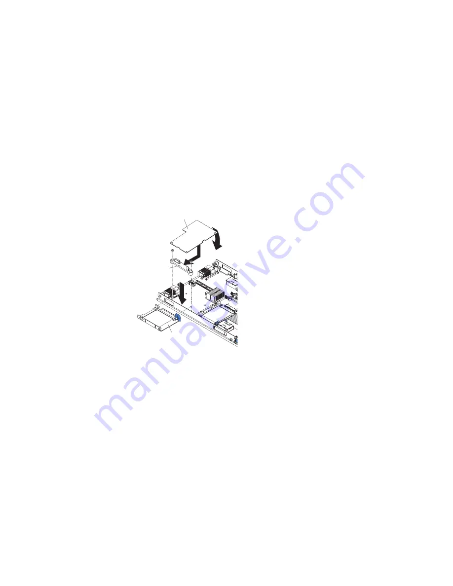
The
following
illustration
shows
how
to
install
a
standard-form-factor
expansion
card.
Hard disk
drive tray
Standard-form-factor
expansion card
PRESS HERE
WHEN
INST
ALLING CARD
Expansion
card
bracket
To
install
a
standard-form-factor
expansion
card,
Complete
the
following
steps:
1.
Read
the
safety
information
that
begins
on
page
v
and
“Installation
guidelines”
on
page
15.
2.
If
the
blade
server
is
installed
in
a
BladeCenter
unit,
remove
it
(see
“Removing
the
blade
server
from
the
BladeCenter
unit”
on
page
17
for
instructions).
3.
Carefully
lay
the
blade
server
on
a
flat,
static-protective
surface.
4.
Open
the
blade
server
cover
(see
“Opening
the
blade
server
cover”
on
page
18
for
instructions).
5.
If
a
Memory
and
I/O
Expansion
Blade
is
installed,
remove
it
(see
“Removing
an
expansion
unit”
on
page
19).
6.
If
you
are
installing
the
expansion
card
in
the
system
board
and
a
drive
is
connected
to
SAS
hard
disk
drive
connector
1,
remove
the
drive
and
tray
(see
“Removing
a
SAS
hard
disk
drive”
on
page
22
for
instructions),
and
save
the
screws
that
secure
the
tray
to
the
system
board.
Store
the
screws
in
a
safe
place.
7.
Install
the
expansion-card
bracket,
if
it
is
not
already
installed.
Secure
the
bracket
to
the
system
board
with
the
screws
from
the
option
kit
or
from
the
removed
drive
tray.
Chapter
3.
Installing
options
31
Summary of Contents for HS21 - BladeCenter - 8853
Page 3: ...BladeCenter HS21 Type 8853 Installation and User s Guide...
Page 60: ...48 BladeCenter HS21 Type 8853 Installation and User s Guide...
Page 78: ...66 BladeCenter HS21 Type 8853 Installation and User s Guide...
Page 79: ......
Page 80: ...Part Number 44W1496 Printed in USA 1P P N 44W1496...


