background image

Welcome.

Thank you for buying an
IBM blade server.

For more information about your
BladeCenter components and
features, you can view the
publications on the

http://www.ibm.com/bladecenter/

Your blade

server features superior
performance, availability,
and scalability.

This
contains information for setting up,
configuring, and using your
blade server.

Additionally, a service information
label is attached to each BladeCenter
unit and blade server. This label
provides a graphical summary of
many of the installation and service
activities that are associated with
each device.

CD or download them from the
IBM Support Web site.

Go to

Installation and User’s Guide

Documentation

Installation and
User’s Guide

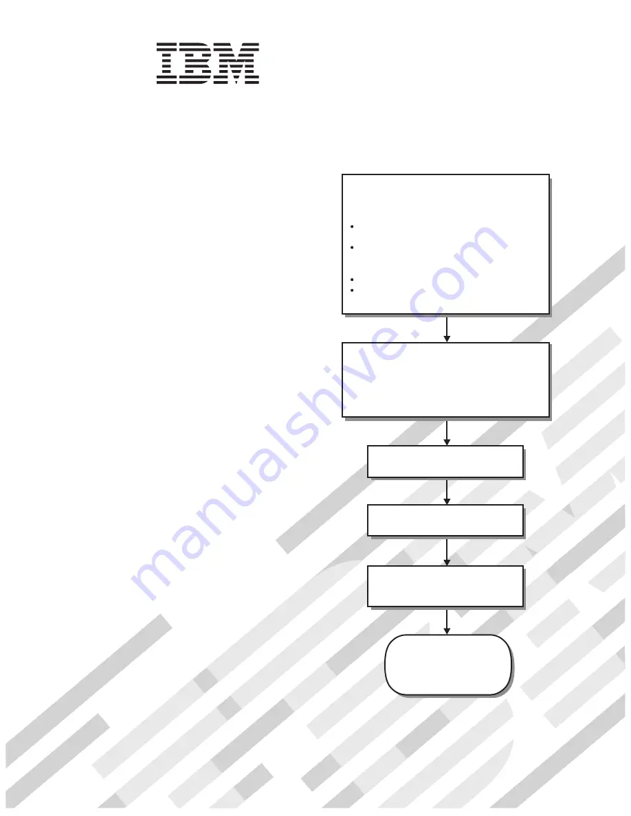
The blade server is now

ready to use. Be sure to

register and profile your

blade server on the

IBM Support Web site.

Before installing the BladeCenter QS21
in a BladeCenter unit, complete the
following procedures:

Install and configure the rack according
to the documentation that came with the rack.
Install the BladeCenter unit into the rack and
configure it, according to the documentation
that comes with the BladeCenter unit.
Supply input power to the BladeCenter unit.
Install the latest firmware in all BladeCenter
components.

Before you install the blade server into the
BladeCenter unit, install optional components
such as memory modules and expansion cards
in the blade server.
Install the blade server in the BladeCenter unit.
See Chapter 4 for more information.

BladeCenter QS21 Type 0792

Install the operating system.
See Chapter 6 for more information.

Install additional applications
according to the instructions that
come with the applications.

Configure the blade server.
See Chapter 5 for more information.

Summary of Contents for QS21 - BladeCenter - 0792

Page 1: ...and profile your blade server on the IBM Support Web site Before installing the BladeCenter QS21 in a BladeCenter unit complete the following procedures Install and configure the rack according to the...

Page 2: ...blem View support telephone numbers at http www ibm com planetwide View information about IBM Support Line at or view support telephone numbers at http www ibm com services sl products http www ibm co...

Page 3: ...BladeCenter QS21 Type 0792 Installation and User s Guide...

Page 4: ...e 81 and the Warranty and Support Information document for your blade server type on the Documentation CD Fifth Edition September 2008 Copyright International Business Machines Corporation 2006 2008 U...

Page 5: ...blade server 15 Installation guidelines 15 Installing the BladeCenter QS21 15 Chapter 4 Installing and removing replaceable units 19 Installation guidelines 19 System reliability guidelines 19 Handli...

Page 6: ...51 Blade server Ethernet controller enumeration 52 Finishing the configuration 52 Chapter 6 Installing the operating system 53 Preparing a boot device 53 Using a boot device on the network 53 Configur...

Page 7: ...Commission FCC statement 85 Industry Canada Class A emission compliance statement 86 Avis de conformit la r glementation d Industrie Canada 86 Australia and New Zealand Class A statement 86 United Kin...

Page 8: ...vi QS21 Installation and User s Guide...

Page 9: ...ert eerst de veiligheidsvoorschriften Ennen kuin asennat t m n tuotteen lue turvaohjeet kohdasta Safety Information Avant d installer ce produit lisez les consignes de s curit Vor der Installation die...

Page 10: ...ed versions of the caution or danger statement in the IBM Safety Information book For example if a caution statement begins with a number 1 translations for that caution statement appear in the IBM Sa...

Page 11: ...quipment when there is evidence of fire water or structural damage v Disconnect the attached power cords telecommunications systems networks and modems before you open the device covers unless instruc...

Page 12: ...containing a lithium battery replace it only with the same module type made by the same manufacturer The battery contains lithium and can explode if not properly used handled or disposed of Do not v T...

Page 13: ...he device v Use of controls or adjustments or performance of procedures other than those specified herein might result in hazardous radiation exposure DANGER Some laser products contain an embedded Cl...

Page 14: ...utton on the device and the power switch on the power supply do not turn off the electrical current supplied to the device The device also might have more than one power cord To remove all electrical...

Page 15: ...ct a service technician Statement 13 DANGER Overloading a branch circuit is potentially a fire hazard and a shock hazard under certain conditions To avoid these hazards ensure that your system electri...

Page 16: ...ash hands after handling ADVERTENCIA El contacto con el cable de este producto o con cables de accesorios que se venden junto con este producto pueden exponerle al plomo un elemento qu mico que en el...

Page 17: ...correction ECC memory per Cell B E chip The system board therefore has a total of 2 GB system memory There is a high speed RAMBUS interface to the processor a PCI X connector for BladeCenter I O exte...

Page 18: ...ompanion chips one per Cell B E chip v 2 x 16 lanes PCIe 2 masters per Cell B E companion chip v 1 PCI X bus per Cell B E companion chip running at 100 MHz v Interface to optional DDR2 memory for use...

Page 19: ...module documentation Boot support The BladeCenter QS21 can boot from v The optical drive of the BladeCenter unit media tray v A SAS storage device typically one or more hard disks attached to the Bla...

Page 20: ...XDR system memory v XDR System memory failure isolation for memory errors to a single memory interface Cell B E 0 or Cell B E 1 attached v DDR2 I O Buffer memory failure isolation to a single DIMM v P...

Page 21: ...dates or documents go to http www ibm com support us en Notices and statements used in this document The caution and danger statements that appear in this document are also in the multilingual Safety...

Page 22: ...in the Safety Information document v Warranty and Support Information This document is in PDF on the IBM Documentation CD It contains information about the terms of the warranty and about service and...

Page 23: ...irements The Documentation CD requires the following minimum hardware and software v Microsoft Windows 2000 Windows XP or Red Hat Linux v 100 MHz microprocessor v 32 MB of RAM v Adobe Acrobat Reader 3...

Page 24: ...system insert the CD into your CD drive then run the following command from the mnt cdrom directory sh runlinux sh The Available Topics list displays all the books for the blade server Some books mig...

Page 25: ...following ways Using the power control button You can press the power control button Figure 3 which is behind the control panel door on the front of the blade server if local power control is enabled...

Page 26: ...the BladeCenter unit has not been turned off the blade server can be turned off in any of the following ways Using the power control button You can press the power control button behind the control pa...

Page 27: ...le or through IBM Director Console Blade error LED This amber LED lights when a system error has occurred in the blade server Power control button Press this button to turn the blade server on or off...

Page 28: ...ent Module Web interface For additional information about errors see Problems indicated by the front panel LEDs on page 60 System board LEDs The BladeCenter QS21 has status LEDs on the system board to...

Page 29: ...M10 Error LED JDIM01 Error LED JDIM 00 Light path diagnostics switch Light box Temperature fault LED System board LED NMI error LED CPU fail LED Light path diagnostics LED NMI CPU SBRD TEMP LP 1 JDIM0...

Page 30: ...14 QS21 Installation and User s Guide...

Page 31: ...onsequences such as incorrect reconfiguration of the blade server Some blade server configuration information and update options are established according to bay number If you reinstall the blade serv...

Page 32: ...her back in the bay that cover the bay opening move out of the way as you insert the blade server 7 Push the release levers on the front of the blade server to the closed position 8 A set of user labe...

Page 33: ...ot already done so turn on the blade server by pressing the power control button on the blade server control panel The power on LED on the blade server changes from the slowly flashing state to a cont...

Page 34: ...18 QS21 Installation and User s Guide...

Page 35: ...eplace any of the hot swappable modules on the rear of the BladeCenter unit v Before you remove a hot swappable blade server from the BladeCenter unit you must shut down the operating system on it by...

Page 36: ...Handle the device carefully holding it by its edges or its frame v Do not touch solder joints pins or exposed printed circuitry v Do not leave the device where others can handle and damage it v While...

Page 37: ...appable bays Therefore you can install or remove the blade server without removing power from the BladeCenter unit However you must turn off the blade server before removing it from the BladeCenter un...

Page 38: ...the blade server and lift the outer cover open see Figure 9 4 If you want to remove the cover carefully lift it from the cover pins and set it aside see Figure 9 Statement 21 CAUTION Hazardous energy...

Page 39: ...s energy is present when the blade server is connected to the power source Always replace the blade cover before installing the blade server Installing the optional InfiniBand card The InfiniBand card...

Page 40: ...board 5 Remove the connector cover 6 Locate the expansion card locator pins at the back of the system board 7 Locate the connector and ball socket on the InfiniBand card Locator pin holes Locking clip...

Page 41: ...If you do not want to install any other options replace the cover and insert the BladeCenter QS21 into the BladeCenter unit Attention The connectors on the system board and the InfiniBand card are not...

Page 42: ...ffer If you fit a single pair of DIMMs you must use slots JDIM00 and JDIM11 The BladeCenter QS21 supports VLP DDR2 512 MB DIMMs only Note The DIMMs are used as memory for the I O buffers only You cann...

Page 43: ...ng cut out on the module 7 Carefully press the module into place until the retaining clips snap into position Make sure that the clips are locked properly 8 Repeat steps 6 and 7 until you have install...

Page 44: ...and the ball stud on the system board 5 Locate the connectors and the ball socket on the SAS card 6 Align the connectors on the system board with the connector on the SAS card Handling areas Figure 1...

Page 45: ...enter unit Installing the BladeCenter PCI Express I O Expansion Unit Important v A BladeCenter QS21 with the BladeCenter PCI Express I O Expansion Unit installed takes up two contiguous slots in the B...

Page 46: ...r on page 22 for further information 3 Remove the connector cover or any optional card from the high speed connector Figure 12 on page 24 shows the location of the high speed connector 4 Lower the exp...

Page 47: ...tery IBM has designed this product with your safety in mind The lithium battery must be handled correctly to avoid possible danger If you replace the battery you must adhere to the following instructi...

Page 48: ...gulations Note See Battery return program on page 84 for more information about battery disposal Complete the following steps to replace the battery 1 Read the safety information beginning on page vii...

Page 49: ...urely 10 Close the blade server cover see Closing the blade server cover on page 36 Statement 21 CAUTION Hazardous energy is present when the blade server is connected to the power source Always repla...

Page 50: ...4 Reinstall the blade server into the BladeCenter unit See Chapter 3 Installing the blade server on page 15 for further information 5 Turn on the blade server See Turning on the blade server on page...

Page 51: ...ly 3 Carefully slide the front bezel assembly onto the blade server as shown in Figure 25 until it clicks into place Note Make sure that you do not pinch any cables when you reinstall the front bezel...

Page 52: ...at the slots at the rear slide down onto the pins at the rear of the blade server as shown Figure 26 Before closing the cover make sure that all components are installed and seated correctly and that...

Page 53: ...e Web based management and configuration program This is your main access method to the blade server The command line interface See Using the command line interface on page 38 for further information...

Page 54: ...ions that appear on the screen Be sure to set the timeout value that you want for your Web session The BladeCenter management and configuration window opens For additional information see the IBM Blad...

Page 55: ...he BladeCenter servers However another utility is provided which in some cases can give more information than that displayed in the Advanced Management Module This is the System Management Services SM...

Page 56: ...0 1024MB CPU1 1024MB Press F1 to display the SMS menu Viewing FRU information The VPD on each blade server contains details about the machine type or model serial number and the universal unique ID Co...

Page 57: ...stem firmware are based on the Open Firmware standard Detailed system information is provided through the Open Firmware device tree You can use the client interface and Run Time Abstraction Services R...

Page 58: ...higher than the version currently installed continue with the updating steps 2 Download the firmware updates 3 Boot the operating system if it is not running already 4 Update the BMC firmware using th...

Page 59: ...also view the firmware level from within the operating system by using the following command xxd proc device tree openprom ibm fw vernum_encoded Output is similar to 0000000 5142 3031 3031 3030 3000 0...

Page 60: ...ver and the operating system 3 Download the package from the IBM support site at http www ibm com support us en The update package has a sh extension 4 Change to the directory where you have downloade...

Page 61: ...e blade server you want to update target and browse to the firmware image file 6 Click on Update 7 The validity of the image is checked then the following screen appears Chapter 5 Configuring the blad...

Page 62: ...olving problems on page 59 for further information about troubleshooting the BladeCenter QS21 blade server You can update the system firmware v Through IBM Director See the IBM Director documentation...

Page 63: ...his has a chg extension v A file containing the update package This has an sh extension v A readme file for the update package This contains specific installation and configuration information v An XM...

Page 64: ...age 42 for instructions Installing the firmware manually If you cannot update the firmware using the update_flash script it is possible to update the firmware manually You can use rtas_flash over proc...

Page 65: ...are two commands you can use to update an old image on PERM v From the Linux prompt issue the following command update_flash c Note The script checks whether the board has booted from the TEMP image...

Page 66: ...1 than the switch modules that are mentioned in this section see the documentation that comes with the Ethernet switch module that you are using Updating the Ethernet controller firmware To update the...

Page 67: ...rectory where you have downloaded the package 4 Run the package with the u option Using the example from above at the command prompt enter brcm_fw_nic_2 0 3 e 1_rhel5_cell sh u During the update proce...

Page 68: ...n external computer on the network connected to the Ethernet switch module If you can ping the external computer the Ethernet controller port that you enabled is associated with the switch module in I...

Page 69: ...tp www alphaworks ibm com tech dim Note IBM may add support for later versions of the operating systems or other operating systems You can check the IBM support Web site or the Information Center topi...

Page 70: ...0 expansion option as SAS attached storage You must configure storage on your DS3200 storage system before you can use it as a SAS boot device Also configure any options such as RAID arrays before ins...

Page 71: ...boot device for the blade server 6 Find out the SAS address for the boot device a Click the Summary tab b Click Storage System Profile c In the Storage Systems Profile notebook click the Controllers...

Page 72: ...drive connected to a server that the BladeCenter QS21 can access through the network If you plan to install the operating system through the Ethernet network see v Integrating the Gigabit Ethernet con...

Page 73: ...drivers If your operating system does not have the required device drivers contact your IBM marketing representative or authorized reseller or see your operating system documentation for additional i...

Page 74: ...58 QS21 Installation and User s Guide...

Page 75: ...ents are connected correctly v The BladeCenter QS21 has the latest firmware updates These include BMC System Gigabit Ethernet controller SAS expansion card if installed InfiniBand high speed expansion...

Page 76: ...nt of the blade can help in isolating problems The table below gives an explanation and a suggested action if required for each LED Table 1 Explanation of LEDs and their states LED State Explanation S...

Page 77: ...to indicate it is communicating with Advanced Management Module If the power on LED to flash rapidly and continues to do so the blade server is not communicating with the management module reseat the...

Page 78: ...es with your BladeCenter unit v Other product specific documentation that comes with the switch module Note For the latest editions of the IBM BladeCenter documentation go to http www ibm com support...

Page 79: ...ement Module 3 Turn on the blade server Note If the temp side is corrupted the boot times out and an automatic reboot occurs after switching to the PERM side If the blade server does not restart you m...

Page 80: ...e that does not allow the firmware to continue the startup process Check the error codes in theQS21 Problem Determination and Service Guide If these do not help resolve the problem contact a service s...

Page 81: ...les Elpida 512MB 3200 MHz XDRlibrary v0 32 Bin A C RevB DualDD Calibrate Done Test Done SYSTEM INFORMATION Processor Cell B E TM DD3 2 3200 MHz I O Bridge Cell BE companion chip DD2 x Timebase 26666 k...

Page 82: ...to change the language that is used to display the SMS menus A screen similar to the following appears PowerPC Firmware Version HEAD SLOF SMS 1 6 c Copyright IBM Corp 2000 2005 2007 All rights reserv...

Page 83: ...en similar to the following appears PowerPC Firmware Version HEAD SLOF SMS 1 6 c Copyright IBM Corp 2000 2005 2007 All rights reserved Network Parameters NET axon 10000000000 plb5 plb4 pcix 4000004600...

Page 84: ...If you wish to cancel and return to the main menu press Esc Adapter Configuration This allows you to set network parameters for the adapter PowerPC Firmware Version HEAD SLOF SMS 1 6 c Copyright IBM C...

Page 85: ...P address in turn Advanced Setup DHCP You do not need to use this option unless your network requires a specific block size or filename PowerPC Firmware Version HEAD SLOF SMS 1 6 c Copyright IBM Corp...

Page 86: ...der If you wish to install or boot from the BladeCenter unit media tray you must first allocate it to the blade server using the Advanced Management Module PowerPC Firmware Version HEAD SLOF SMS 1 6 c...

Page 87: ...oot devices in list order until it finds a boot device If it does not an error is generated and placed in the Advanced Management Module You may only list boot devices if they are allocated or availab...

Page 88: ...choose a device type the number and press Enter To save your selection press M to return to the menu Firmware Boot Side Options Normally the BladeCenter QS21 boots from the Temporary side and you sho...

Page 89: ...ory Creating common NVRAM partition C0880 Could not find SAS partition in NVRAM created Adapters on 000001460ec00000 00 0800 D 14e4 16a8 network ethernet 00 0900 D 14e4 16a8 network ethernet Adapters...

Page 90: ...o enter the machine type or model and serial number Boot does not continue until the information is provided To enter new FRU information complete the following steps 1 Using a Telnet or SSH client co...

Page 91: ...ng to the instructions on the screen and press Enter to continue 5 You must confirm the model number PowerPC Firmware Version HEAD SLOF SMS 1 6 c Copyright IBM Corp 2000 2005 2007 All rights reserved...

Page 92: ...MS 1 6 c Copyright IBM Corp 2000 2005 2007 All rights reserved Number entered is ABCDEFG Accept number Enter y or Y to accept or n or N to decline Select Navigation key Type y or Y and press Enter to...

Page 93: ...007 All rights reserved Change SAS Boot Device Address Current SAS Disk Address Default 0 0 Navigation Keys M return to Main Menu ESC key return to previous screen X eXit System Management Services Ty...

Page 94: ...in Menu ESC key return to previous screen X eXit System Management Services Type new LUN Id in hexadecimal and press Enter or select navigation key The LUN Id can be obtained from the Storage System P...

Page 95: ...BM product The documentation that comes with BladeCenter systems also describes the diagnostic tests that you can perform Most BladeCenter systems operating systems and programs come with documentatio...

Page 96: ...es see http www ibm com services us or see http www ibm com planetwide for support telephone numbers In the U S and Canada call 1 800 IBM SERV 1 800 426 7378 Hardware service and support You can recei...

Page 97: ...0504 1785 U S A INTERNATIONAL BUSINESS MACHINES CORPORATION PROVIDES THIS PUBLICATION AS IS WITHOUT WARRANTY OF ANY KIND EITHER EXPRESS OR IMPLIED INCLUDING BUT NOT LIMITED TO THE IMPLIED WARRANTIES O...

Page 98: ...eed indicates the internal clock speed of the microprocessor other factors also affect application performance CD or DVD drive speed is the variable read rate Actual speeds vary and are often less tha...

Page 99: ...udar a los propietarios de equipos a reciclar sus productos de TI Se puede encontrar informaci n sobre las ofertas de reciclado de productos de IBM en el sitio web de IBM http www ibm com ibm environm...

Page 100: ...r area For information on disposal of batteries outside the United States go to http www ibm com ibm environment products index shtml or contact your local waste disposal facility In the United States...

Page 101: ...ative For California Perchlorate material special handling may apply See http www dtsc ca gov hazardouswaste perchlorate The foregoing notice is provided in accordance with California Code of Regulati...

Page 102: ...ische Vertr glichkeit in den EU Mitgliedsstaaten und h lt die Grenzwerte der EN 55022 Klasse A ein Um dieses sicherzustellen sind die Ger te wie in den Handb chern beschrieben zu installieren und zu b...

Page 103: ...roduct including the fitting of non IBM option cards This product has been tested and found to comply with the limits for Class A Information Technology Equipment according to CISPR 22 European Standa...

Page 104: ...Japanese Voluntary Control Council for Interference VCCI statement Korean Class A warning statement 88 QS21 Installation and User s Guide...

Page 105: ...ttery 13 I O expansion card 13 input output 36 memory 13 microprocessor 13 system board 13 controller enumeration 52 controller continued Ethernet 49 cover closing 29 36 opening 22 removing 22 D dange...

Page 106: ...nd statements 5 O operating system network connection requirements 53 option installing 19 oversubscription power domain 3 P PERM image updating 49 using to recover TEMP image 63 ports input output 36...

Page 107: ...EDs 12 system firmware 41 PERM image 49 recovering 63 startup process errors 64 TEMP image 49 updating 46 updating image 49 updating image manually 48 System Management Services 65 See SMS system reli...

Page 108: ...92 QS21 Installation and User s Guide...

Page 109: ......

Page 110: ...Part Number 40M2416 Printed in USA 1P P N 40M2416...

Reviews: