background image

 Chapter 3. Operating and caring for your computer   13

Keep diskettes away from magnets or devices that create a strong magnetic 
field, such as electric motors and generators. Diskettes are sensitive to 
magnets found in television sets, telephones, stereo speakers, and other such 
items. A magnetic field can erase the data on your diskettes. Do not set 
diskettes on the monitor or use magnets to attach notes to your computer.

Do not store diskettes at high temperatures, low temperatures, or in direct 
sunlight. Temperatures ranging from 4° to 53°C (39° to 127°F) are 
acceptable for 3.5-inch diskettes. Keep diskettes away from heat. The plastic 
outer covering might warp, damaging the diskette.

Inserting and removing diskettes

To insert a 3.5-inch diskette, hold the diskette with the label facing up and insert 
the end with the protective slide first. Push the diskette into the diskette drive 
until the diskette clicks into place.

To remove the diskette, press the eject button and slide the diskette out of the 
drive. Do not remove the diskette while the in-use light is on.

Write-protecting diskettes

It is possible to accidentally format a diskette or unintentionally write data to it. 
Important information can be written over or lost. For this reason, it is a good 
idea to write-protect important diskettes. You can read data from a write-
protected diskette, but you cannot erase or change the data.

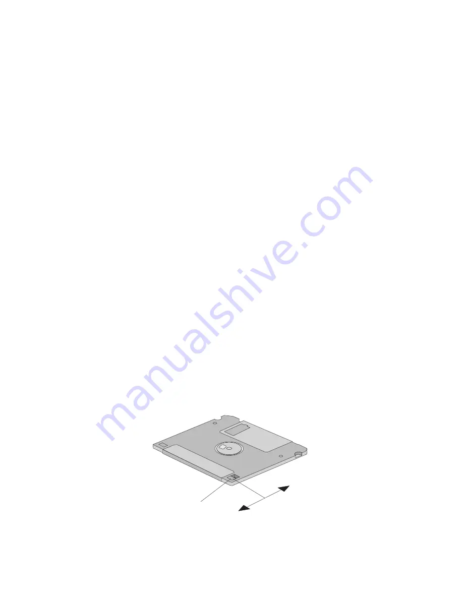
Most 3.5-inch diskettes have a write-protect switch that can be used to prevent 
data from being written to or erased from the diskette. If a 3.5-inch diskette does 
not have a write-protect switch, it is permanently write-protected.

The write-protect switch is located on the back of 3.5-inch diskettes.

To allow writing to the diskette, slide the switch so the write-protect window 
is covered.

Write-protect

switch

Summary of Contents for Aptiva E2270

Page 1: ...IBM Aptiva E Personal Computer Machine Type 2270...

Page 2: ...d Note to U S Government Users Restricted Rights Use duplication or disclosure restricted by GSA ADP Schedule Contract with IBM Corp Before using this information and the product it supports be sure t...

Page 3: ...ings 6 Setting the voltage selection switch 7 Connecting cables 7 Turning on power 9 Chapter 3 Operating and caring for your computer 11 Controls and status indicators 11 Shutting down 12 Using disket...

Page 4: ...echnical Troubleshooting 31 BIOS features 31 Accessing BIOS 32 Monitoring the power on self test POST 32 Most frequently asked BIOS questions 32 Device troubleshooting charts 32 Diskette drive problem...

Page 5: ...ssing date data 52 Trademarks 53 Electronic emission notices 54 Class B Notices 54 Federal Communications Commission FCC Statement 54 Federal Communications Commission FCC and telephone company re qui...

Page 6: ...iv IBM PC User Guide...

Page 7: ...receptacles Remove all cables from devices Attach power cord to outlet First attach all cables to devices Electrical current from power telephone and communication cables is hazardous To avoid shock...

Page 8: ...rs tension Le courant lectrique provenant des c bles d alimentation t lephoniques et de transmission peut pr senter un danger Pour viter tout risque de choc lectrique connectez et d connectez ces c bl...

Page 9: ...Repair or disassemble Dispose of the battery as required by local ordinances or regulations ATTENTION Danger d explosion en cas de remplacement incorrect de la batterie Remplacer uniquement par une ba...

Page 10: ...he network interface Use caution when installing or modifying telephone lines Avoid using a telephone other than a cordless type during an electrical storm There may be a remote risk of electric shock...

Page 11: ...hazardous laser radiation There are no serviceable parts inside the CD ROM DVD ROM or CDR drive Do not remove the drive covers Some CD ROM DVD ROM and CDR drives contain an embedded Class 3A or Class...

Page 12: ...ppel du personnel qualifi Certaines unit s de CD ROM DVD ROM CDR peuvent contenir une diode laser de classe 3A ou 3B Tenez compte de la consigne qui suit DANGER Rayonnement laser lorsque le carter est...

Page 13: ...ar with your IBM Personal Computer and its features It describes how to set up operate maintain and install options in your computer In the unlikely event you experience problems you will find helpful...

Page 14: ...xii IBM PC User Guide...

Page 15: ...is section provides an overview of the computer features preinstalled software and specifications Identifying your computer The best way to identify your computer is through use of your machine type n...

Page 16: ...ust independently and provide good support The seat should have a curved front to relieve pressure on the thighs Adjust the seat so that your thighs are parallel to the floor and your feet are either...

Page 17: ...r screen periodically using a soft cloth moistened with a nonabrasive liquid glass cleaner Air circulation Your computer and monitor produce heat The computer has a fan that pulls in fresh air and for...

Page 18: ...4 IBM PC User Guide...

Page 19: ...l cable and power cord If you are missing an item contact your place of purchase Selecting a location for your computer Make sure you have an adequate number of properly grounded electrical outlets fo...

Page 20: ...settings This section shows the location of the connectors on the back of your computer You might not have all of the connectors shown USB 1 USB 2 Video MIDI Joystick Mouse Keyboard Serial 1 Parallel...

Page 21: ...ch to 230 V Connecting cables The connectors on the rear of the computer have color coded icons to help you connect the cables properly Use the following steps to connect your cables 1 Connect the key...

Page 22: ...versal Serial Bus USB device Any optional device such as speakers microphones or headphones Connect the phone line connector for models with a modem If your computer comes with an Ethernet adapter con...

Page 23: ...and then plug the cords into properly grounded electrical outlets Turning on power Turn on the monitor and other external devices first then press and release the power switch on the computer You see...

Page 24: ...10 IBM PC User Guide...

Page 25: ...ollowing illustration show the controls and status indicators The following list describes the controls and status indicators for your computer Power switch Press this switch to turn your computer on...

Page 26: ...nsaved data or damage to your software programs See your operating system documentation for instructions Using diskettes You can use 3 5 inch diskettes in the diskette drive of your computer The infor...

Page 27: ...the end with the protective slide first Push the diskette into the diskette drive until the diskette clicks into place To remove the diskette press the eject button and slide the diskette out of the d...

Page 28: ...e dust Excessive vibration or sudden shock An inclined surface Direct sunlight Do not insert any object other than a CD into the drive Before moving the computer remove the CD from the drive Handling...

Page 29: ...gency eject hole located on the front of the CD ROM drive Using audio features Your computer has an integrated audio controller The audio controller provides you with the ability to record and play ba...

Page 30: ...ent Make sure it rests on a flat sturdy surface Do not place items on top of the monitor or cover any of the vents in the monitor or computer These vents allow air flow to keep your computer and monit...

Page 31: ...e retainer on the bottom of the mouse by moving it in the direction indicated by the arrow on the retainer 4 Turn the mouse right side up and the retainer and ball will drop out 5 Wash the ball in war...

Page 32: ...iscs and tapes from the drives 3 Shut down your operating system and turn off the computer and all attached devices Your hard disk drive automatically parks the read write heads in a nondata area This...

Page 33: ...dges Never touch any exposed circuitry Prevent others from touching components When you install a new option touch the static protective package containing the option to a metal expansion slot cover o...

Page 34: ...d disk Diskette drives and other removable media drives Tools required To install or remove some options in your computer you will need a phillips head screwdriver Additional tools might be needed for...

Page 35: ...of internal components Do not operate your computer with the cover removed Working with options on the system board This section provides instructions for installing options and setting the diskette w...

Page 36: ...variety of devices that are IBM installed or that you can install later Refer to the following illustration for the location of parts on the system board Note An illustration of the system board and a...

Page 37: ...in any combination of supported SDRAM DIMMs Note To locate the memory connectors on the system board see the illustration on page 22 or the system board label inside your computer Note You might have...

Page 38: ...Reinstall any adapters that you removed See Installing adapters on page 25 for instructions to reinstall the adapter Working with adapters This section provides information and instructions for instal...

Page 39: ...expansion slot 2 Remove the adapter from its static protective package 3 Install the adapter into the appropriate slot on the system board 4 Reinstall the slot cover plate and install the screw that...

Page 40: ...a You can add drives to your computer to increase storage capacity and to enable your computer to read other types of media Some of the different drives available for your computer are Hard disk drive...

Page 41: ...es and insert the two screws 5 Connect the power and signal cables to the drive Completing the installation After working with options you need to reinstall any removed parts replace the side panel an...

Page 42: ...l forward so the retainer clips engage the chassis 6 Insert the two phillips head screws into the holes at the top and bottom of the side panel and the chassis and tighten 7 Reconnect the external cab...

Page 43: ...you install or remove Plug and Play adapters this information is interpreted by the basic input output system BIOS which supports Plug and Play technology If the required resources are available the B...

Page 44: ...30 IBM PC User Guide...

Page 45: ...operating system documentation supplied with your computer If you have installed software applications yourself see the documentation supplied with the software The following tools are available to di...

Page 46: ...S questions How do I change the mode of the parallel port Select the BIOS menu Peripheral Setup How do I change the startup sequence Select the BIOS menu Advanced CMOS Setup How do I disable the onboa...

Page 47: ...lems on page 34 General General problems on page 38 Intermittent Intermittent problems on page 38 Keyboard mouse or pointing device Keyboard mouse or pointing device problems on page 39 Memory Memory...

Page 48: ...e Configuration Setup Utility program to verify this 3 The diskette you are using is good and not damaged Try inserting another diskette if you have one 4 The diskette is inserted correctly with its l...

Page 49: ...at is not supported by your monitor might damage it You can reset the refresh rate through your operating system See your operating system documentation for further information on monitor settings If...

Page 50: ...es so that they are at least 305 mm 12 in apart Also when relocating the monitor be sure it is at least 76 mm 3 in from the diskette drives to prevent diskette drive read write errors c Turn on the mo...

Page 51: ...nk screen Verify that 1 The monitor power cord is plugged into a working electrical outlet 2 The monitor is turned on and the Brightness and Contrast controls are adjusted correctly 3 The monitor sign...

Page 52: ...the problem contact IBM technical support Problems such as indicator lights not working Contact IBM technical support Intermittent problems Action A problem occurs only occasionally and is difficult...

Page 53: ...gs on page 6 If this does not correct the problem contact IBM technical support The mouse or pointing device does not work Verify that 1 The mouse or pointing device cable is securely attached to the...

Page 54: ...t the memory available for its use For example if the system uses 4MB of memory for video and the total system memory is 64MB Windows will report 60MB Verify that 1 You have installed the correct type...

Page 55: ...ed are installed correctly See Installing files from Option Diskettes on page 45 for information about installing option files 4 You have not loosened any other installed options or cables 5 If the op...

Page 56: ...tion verify that 1 The cables for all external SCSI options are connected correctly 2 The last option in each SCSI chain or the end of the SCSI cable is terminated correctly 3 All external SCSI option...

Page 57: ...ecurely connected to the correct parallel serial or USB port on the computer See Cable connections and switch settings on page 6 3 You have assigned the printer port correctly in your operating system...

Page 58: ...ress conflict 2 The software is designed to operate on your computer 3 Other software works on your computer 4 The software you are using works on another computer If you received any error messages w...

Page 59: ...the computer The battery requires no charging or maintenance throughout its life however no battery lasts forever If the battery fails the date time and configuration information including passwords a...

Page 60: ...25 for instructions for replacing adapters 8 Replace the cover and plug in the power cord Note When the computer is turned on for the first time after battery replacement an error message might be di...

Page 61: ...without notice Service support With the original purchase of an IBM hardware product you have access to extensive support coverage During the IBM hardware product warranty period you may call the IBM...

Page 62: ...proof of purchase to obtain warranty service Please have the following information ready when you call Machine Type 2270 Serial number please refer to page 1 for instructions on how to find your seria...

Page 63: ...umentation including README files for the operating system or application program Getting customer support and service Purchasing an IBM PC hardware product entitles you to standard help and support d...

Page 64: ...for service Arranging for shipment of customer replaceable parts Please have the following information ready when you call Machine Type 2270 Serial number please refer to page 1 for instructions on h...

Page 65: ...furnishing of this document does not give you any license to these patents You can send license inquiries in writing to IBM Director of Licensing IBM Corporation North Castle Drive Armonk NY 10504 17...

Page 66: ...Actual results may vary Users of this document should verify the applicable data for their specific environment Processing date data This IBM hardware product and IBM software products that might be...

Page 67: ...The following terms are trademarks of the IBM Corporation in the United States or other countries or both HelpCenter IBM IntelliStation Netfinity Other company product and service names may be tradema...

Page 68: ...erence by one or more of the following measures Reorient or relocate the receiving antenna Increase the separation between the equipment and receiver Connect the equipment into an outlet on a circuit...

Page 69: ...l to the exterior of the computer in which you install the IBM modem or you may attach the label to the exter nal DAA if you have one Place the label in a location that is easily accessi ble should yo...

Page 70: ...specify service arrangement USOC RJ11C Canadian Department of Communications certification label NOTICE The Industry Canada label identifies certified equipment This certi fication means that the equi...

Page 71: ...de l utilisateur Avant d installer ce mat riel l utilisateur doit s assurer qu il est permis de le rac corder aux installations de l entreprise locale de t l communications Le mat riel doit galement t...

Page 72: ...ed by Under writer s Laboratories UL and certified by the Canadian Standards Association CSA For units intended to be operated at 115 volts Use a UL listed and CSA certified cord set consisting of a m...

Page 73: ...16 keyboard 16 monitor 16 mouse 17 computer locating 3 computer location 5 D DIMMs dual inline memory mod ules 23 diskette drive 12 diskette drives eject button 12 13 indicator light 12 problems solvi...

Page 74: ...ointing device problems 39 POST description of 32 power switch 9 11 printer problems 43 problem solving 33 processor location 22 R removing side panel 21 S safety electrical v service support 47 setti...

Page 75: ...Part Number 121048 001 Printed in U S A May 2000 PN 121048 001 121048 001...

Reviews: