1.
Review the safety precautions in Statement 1 and Statement 5 in “Safety
information” on page 123.
2.
Review the information in “System reliability considerations” on page 56 and
the documentation that comes with the option.
3.
Turn off the server and peripheral devices, and disconnect all external cables
and power cords; then, remove the cover (see “Removing the side cover” on
page 57 for details).
4.
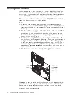
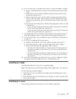
Select the connector in which to install the DIMM.
5.
Touch the static-protective package containing the DIMM to any unpainted
metal surface on the server. Then, remove the DIMM from the package.
Attention:
To avoid breaking the retaining clips or damaging the DIMM
connectors, handle the clips gently.
6.
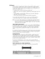
Install the DIMM:
a.
Open the retaining clips on the connector.
b.
Turn the DIMM so that the pins align correctly with the connector.
c.
Insert the DIMM into the connector by pressing on one edge of the DIMM
and then on the other edge of the DIMM. Ensure that you press straight
into the connector.
d.
Make sure that the retaining clips are in the closed position. If a gap exists
between the DIMM and the retaining clips, the DIMM has not been
properly installed. In this case, open the retaining clips and remove the
DIMM; then, reinsert the DIMM.
7.
If you have other options to install or remove, do so now; otherwise, go to
“Installing the cover” on page 79.
Attention:
When you restart the server, the system displays a message indicating
that the memory configuration has changed.
v
If you installed additional memory, start the Configuration /Setup Utility
program and select
Save Settings
.
v
If you just replaced a failed DIMM, you must start the Configuration /Setup
Utility program, select
Advanced Setup
, select
Memory Settings
, highlight the
connector or bank of connectors that you want to enable, then select
Enable
.
v
In some memory configurations, the 3-3-3 beep code might sound during POST
followed by a blank screen. If this occurs, you must restart the server three times
to force the system BIOS to reset the memory connector or bank of connectors
from Disabled to Enabled.
Installing and removing a microprocessor
The server comes with one microprocessor, which is installed on the system board.
If you install an additional microprocessor kit, the server can operate as a
symmetric multiprocessing (SMP) server. With SMP, certain operating systems and
application programs can distribute the processing load between the
microprocessors. This enhances performance for database and point-of-sale
applications, integrated manufacturing solutions, and other applications.
Notes:
1.
Before you install a new microprocessor, review the documentation that comes
with the microprocessor, so that you can determine whether you need to
update the server basic input/output system (BIOS). The latest level of BIOS
for the server is available through the World Wide Web.
Installing options
73
Summary of Contents for 8645 - Eserver xSeries 220
Page 1: ...Hardware Maintenance Manual xSeries 220 Type 8645...
Page 2: ......
Page 3: ...Hardware Maintenance Manual xSeries 220 Type 8645...
Page 18: ...10 Hardware Maintenance Manual xSeries 220 Type 8645...
Page 36: ...28 Hardware Maintenance Manual xSeries 220 Type 8645...
Page 58: ...50 Hardware Maintenance Manual xSeries 220 Type 8645...
Page 102: ...94 Hardware Maintenance Manual xSeries 220 Type 8645...
Page 141: ...Related service information 133...
Page 142: ...134 Hardware Maintenance Manual xSeries 220 Type 8645...
Page 143: ...Related service information 135...
Page 144: ...136 Hardware Maintenance Manual xSeries 220 Type 8645...
Page 145: ...Related service information 137...
Page 146: ...138 Hardware Maintenance Manual xSeries 220 Type 8645...
Page 147: ...Related service information 139...
Page 148: ...140 Hardware Maintenance Manual xSeries 220 Type 8645...
Page 158: ...150 Hardware Maintenance Manual xSeries 220 Type 8645...
Page 159: ...Related service information 151...
Page 160: ...152 Hardware Maintenance Manual xSeries 220 Type 8645...
Page 167: ......

