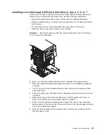
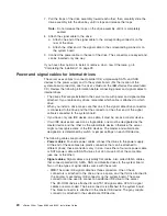
background image

Handling


static-sensitive


devices


Attention:


Static


electricity


can


damage


the


server


and


other


electronic


devices.


To


avoid


damage,


keep


static-sensitive


devices


in


their


static-protective


packages


until


you


are


ready


to


install


them.


To


reduce


the


possibility


of


electrostatic


discharge,


observe


the


following


precautions:


v


Limit


your


movement.


Movement


can


cause


static


electricity


to


build


up


around


you.


v


The


use


of


a


grounding


system


is


recommended.


For


example,


wear


an


electrostatic-discharge


wrist


strap,


if


one


is


available.


Always


use


an


electrostatic-discharge


wrist


strap


or


other


grounding


system


when


working


inside


the


server


with


the


power


on.


v


Handle


the


device


carefully,


holding


it


by


its


edges


or


its


frame.


v


Do


not


touch


solder


joints,


pins,


or


exposed


circuitry.


v


Do


not


leave


the


device


where


others


can


handle


and


damage


it.


v


While


the


device


is


still


in


its


static-protective


package,


touch


it


to


an


unpainted


metal


surface


on


the


outside


of


the


server


for


at


least


2


seconds.


This


drains


static


electricity


from


the


package


and


from


your


body.


v


Remove


the


device


from


its


package


and


install


it


directly


into


the


server


without


setting


down


the


device.


If


it


is


necessary


to


set


down


the


device,


put


it


back


into


its


static-protective


package.


Do


not


place


the


device


on


the


server


cover


or


on


a


metal


surface.


v


Take


additional


care


when


handling


devices


during


cold


weather.


Heating


reduces


indoor


humidity


and


increases


static


electricity.


Chapter


2.


Installing


options


9

Summary of Contents for 8485E2U

Page 1: ...page Cable the server and options Start the server Install options Drives Adapters Memory Did the server start correctly Yes No Use ServerGuide to set up and configure hardware Did configuration compl...

Page 2: ...tions and verify that all optional devices you installed are on the ServerProven list at http www ibm com servers eserver serverproven compat us Is the server working correctly Is the problem solved H...

Page 3: ...xSeries 206m Types 8485 and 8490 Installation Guide...

Page 4: ...ge 79 and the Warranty and Support Information document on the IBM xSeries Documentation CD Third Edition October 2006 Copyright International Business Machines Corporation 2006 All rights reserved US...

Page 5: ...k drive in bay 4 5 6 or 7 23 Power and signal cables for internal drives 24 Installing an adapter 25 Completing the installation 28 Reinstalling the two piece bezel 28 Reinstalling the side cover 30 C...

Page 6: ...es 79 Edition notice 79 Trademarks 80 Important notes 80 Product recycling and disposal 81 Battery return program 82 Electronic emission notices Class A 83 Federal Communications Commission FCC statem...

Page 7: ...alleert eerst de veiligheidsvoorschriften Ennen kuin asennat t m n tuotteen lue turvaohjeet kohdasta Safety Information Avant d installer ce produit lisez les consignes de s curit Vor der Installation...

Page 8: ...ons of the caution or danger statement in the IBM Safety Information book For example if a caution statement begins with a number 1 translations for that caution statement appear in the IBM Safety Inf...

Page 9: ...quipment when there is evidence of fire water or structural damage v Disconnect the attached power cords telecommunications systems networks and modems before you open the device covers unless instruc...

Page 10: ...hium battery replace it only with the same module type made by the same manufacturer The battery contains lithium and can explode if not properly used handled or disposed of Do not v Throw or immerse...

Page 11: ...he device v Use of controls or adjustments or performance of procedures other than those specified herein might result in hazardous radiation exposure DANGER Some laser products contain an embedded Cl...

Page 12: ...n the device and the power switch on the power supply do not turn off the electrical current supplied to the device The device also might have more than one power cord To remove all electrical current...

Page 13: ...ect a problem with one of these parts contact a service technician Statement 12 CAUTION The following label indicates a hot surface nearby Statement 13 DANGER Overloading a branch circuit is potential...

Page 14: ...er and birth defects or other reproductive harm Wash hands after handling ADVERTENCIA El contacto con el cable de este producto o con cables de accesorios que se venden junto con este producto pueden...

Page 15: ...s described in this document 1 Go to http www ibm com support 2 Under Search technical support type 8485 or 8490 depending on the machine type for your server model and click Search The server comes w...

Page 16: ...cannot be duplicated by a locksmith If you lose them order replacement keys from the key manufacturer The key serial number and the telephone number of the manufacturer are on a tag that is attached t...

Page 17: ...n Browser v If Autostart is enabled insert the CD into the CD drive The Documentation Browser starts automatically v If Autostart is disabled or is not enabled for all users use one of the following p...

Page 18: ...ices provide important tips guidance or advice v Important These notices provide information or advice that might help you avoid inconvenient or problem situations v Attention These notices indicate p...

Page 19: ...anagement controller mini BMC v Broadcom 5721 10 100 1000 Ethernet controller on the system board with RJ 45 Ethernet port v Two serial ports v One parallel port v Four port Serial ATA controller v On...

Page 20: ...p components See the instructions for removing or installing a specific hot swap component for any additional procedures that you might have to perform before you remove or install the component The f...

Page 21: ...lectrical outlets for the server monitor and other devices v Back up all important data before you make changes to disk drives v Have a small flat blade screwdriver available v You do not have to turn...

Page 22: ...You have replaced a hot swap drive within 2 minutes of removal Working inside the server with the power on Attention Static electricity that is released to internal server components when the server...

Page 23: ...power on v Handle the device carefully holding it by its edges or its frame v Do not touch solder joints pins or exposed circuitry v Do not leave the device where others can handle and damage it v Wh...

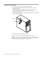
Page 24: ...its side 4 Unlock the side cover then press the cover release latch down as indicated by the two arrows on the latch Cover release latch Key lock 5 Lift the side cover off the server and set it aside...

Page 25: ...ezel you do not have to remove the side cover However the side cover must be unlocked To remove the two piece bezel complete the following steps 1 Unlock the side cover 2 Remove the side cover see Rem...

Page 26: ...hen rotate the upper bezel to the right side of the server to disengage the two right side tabs from the chassis Set the upper bezel aside For instructions for reinstalling the two piece bezel see Rei...

Page 27: ...rmation see the User s Guide on the IBM xSeries Documentation CD v For two way memory interleaving DIMMs must be installed in matched pairs If one DIMM is installed in the DIMM 1 connector when you in...

Page 28: ...p which could result in the loss of data To avoid this potential problem always use an electrostatic discharge wrist strap or other grounding system when working inside the server with the power on To...

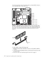
Page 29: ...inted metal surface on the server Then remove the new DIMM from the package 7 Turn the DIMM so that the DIMM keys align correctly with the slot 8 Insert the DIMM into the connector by aligning the edg...

Page 30: ...ay 4 Some non hot swap SATA models might come with an IDE CD ROM drive in bay 1 and a non hot swap SATA hard disk drive in bay 4 Some hot swap SATA models might come with an IDE CD ROM drive in bay 1...

Page 31: ...PCI Express and PCI X slots covered or occupied When you install a drive or PCI PCI Express or PCI X adapter save the EMC shield and filler panel from the bay or the PCI PCI Express or PCI X adapter...

Page 32: ...Class 3B laser diode Note the following Laser radiation when open Do not stare into the beam do not view directly with optical instruments and avoid direct exposure to the beam Class 1 Laser Product L...

Page 33: ...or 7 This procedure applies only to server models that have hot swap hard disk drives Some server models come with SAS or SATA hot swap hard disk drives Before you install a hot swap hard disk drive r...

Page 34: ...andle is open b Align the drive assembly with the guide rails in the bay c Gently push the drive assembly into the bay until the drive stops d Push the tray handle to the closed locked position e Chec...

Page 35: ...p models In the typical configuration the standard hard disk drives and backplane are connected to channel A Device ID Drive bay 4 0 Drive bay 5 1 Drive bay 6 2 Drive bay 7 3 Installing a simple swap...

Page 36: ...static protective package that contains the drive to any unpainted metal surface on the server then remove the drive from the package and place it on a static protective surface 6 Align the drive asse...

Page 37: ...sk drive To install a non hot swap SATA hard disk drive complete the following steps 1 Read the safety information that begins on page v and Installation guidelines on page 7 2 Turn off the server and...

Page 38: ...nected to the system board v If you have only one IDE device on a cable it must be set as a master device v If two IDE devices are used on a single cable one must be designated as the master device an...

Page 39: ...at comes with the adapter and follow those instructions in addition to the instructions in this section If you need to change the switch setting or jumper settings on the adapter follow the instructio...

Page 40: ...see http www ibm com servers eserver serverproven compat us For the locations of the expansion slots on the system board and the optional PCI X expansion card see the User s Guide on the IBM xSeries...

Page 41: ...the adapter to any unpainted metal surface on the server Then remove the adapter from the static protective package Avoid touching the components and gold edge connectors on the adapter 8 If you are i...

Page 42: ...wo piece bezel reinstall the side cover connect all the cables and for certain options run the Configuration Setup Utility program Follow the instructions in this section Reinstalling the two piece be...

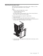
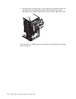
Page 43: ...chassis a Insert the two bottom tabs on the lower bezel into the matching holes in the front of the chassis b Tilt the top of the lower bezel into position on the chassis until the lower bezel locks...

Page 44: ...that all cables adapters and other components are installed and seated correctly and that you have not left loose tools or parts inside the server Also make sure that all internal cables are correctly...

Page 45: ...cable end with the color of the connector For example match a blue cable end with a blue panel connector a red cable end with a red connector and so on The following illustration shows the input outpu...

Page 46: ...guration settings See Chapter 4 Configuring the server on page 39 for additional information Some options have device drivers that you must install For information about installing device drivers see...

Page 47: ...supply or the LED itself has failed Note If this LED is off it does not mean that there is no electrical power in the server The LED might be burned out To remove all electrical power from the server...

Page 48: ...t the associated hard disk drive is in use When the drive is removed this LED also is visible on the SAS backplane next to the drive connector The backplane is the printed circuit board behind drive b...

Page 49: ...vice to this connector Keyboard connector Connect a keyboard PS 2 to this connector Serial 1 connector Connect a 9 pin serial device to this connector Parallel connector Connect a parallel device to t...

Page 50: ...and start the by pressing the power control button The server can also be turned on in any of the following ways v If a power failure occurs while the server is turned on the server will restart autom...

Page 51: ...system the server will be turned off automatically v You can press the power control button to start an orderly shutdown of the operating system and turn off the server if your operating system suppor...

Page 52: ...38 xSeries 206m Types 8485 and 8490 Installation Guide...

Page 53: ...se programs see Configuring the server in the User s Guide on the IBM xSeries Documentation CD Using the ServerGuide Setup and Installation CD The ServerGuide Setup and Installation CD provides state...

Page 54: ...tes 1 RAID options and HostRAID are not supported on the SCO 6 0 and UnixWare 7 14 operating systems 2 A configuration conflict error code 1801 might occur if SATA RAID and SAS SATA RAID are both enab...

Page 55: ...ted Serial ATA controller simple swap SATA models with integrated SATA RAID support RAID level 0 and level 1 with the option of having a hot spare drive An optional ServeRAID controller provides addit...

Page 56: ...own and select SATA RAID Enable 6 Select Enabled 7 Press Esc then select Yes to save your changes Using the Serial ATA HostRAID feature The instructions in this section are for using the Array Configu...

Page 57: ...ATA controller complete the following steps 1 Start the Array Configuration Utility 2 From the Array Configuration Utility window select Manage Arrays 3 Select an array and press Enter 4 Press Esc to...

Page 58: ...the server 2 When the prompt Press CTRL A for SAS SATA Configuration Utility appears press Ctrl A If you have set an administrator password you are prompted to type the password 3 Select SerialSelect...

Page 59: ...st run ServeRAID Manager in Startable CD mode as described in the instructions in this section If you install a different type of RAID adapter in the server use the method that is described in the ins...

Page 60: ...custom configuration complete the following steps 1 In the ServeRAID Manager tree click the controller 2 From the toolbar click Create 3 Click Custom configuration 4 Click Next 5 Click the applicable...

Page 61: ...a 10 Mbps 100 Mbps or 1 Gbps network and provides full duplex FDX capability which enables simultaneous transmission and reception of data on the network If the Ethernet ports in the server support au...

Page 62: ...48 xSeries 206m Types 8485 and 8490 Installation Guide...

Page 63: ...hen you are using the ServerGuide Setup and Installation CD For more information see ServerGuide problems on page 63 v Troubleshooting tables These tables list problem symptoms and steps to correct th...

Page 64: ...ved v See the parts listing in the Problem Determination and Service Guide to determine which components are customer replaceable units CRU and which components are field replaceable units FRU v If an...

Page 65: ...iguration information or CMOS random access memory RAM checksum failure 1 Run the Configuration Setup Utility program select Load Default Settings and save the settings 2 Reseat the following componen...

Page 66: ...Problem Determination and Service Guide on the IBM xSeries Documentation CD 2 Replace the Remote Supervisor Adapter II 184 Power on password damaged 1 Run the Configuration Setup Utility program selec...

Page 67: ...r run the Configuration Setup Utility program and enable the DIMM 2 Make sure that the DIMM is installed correctly see Installing a memory module on page 13 3 Replace the DIMM 4 Trained service techni...

Page 68: ...technician Error code Description Action 1600 The service processor is not functioning Note Depending on which device is installed the service processor is the optional Remote Supervisor Adapter II o...

Page 69: ...x see Running the diagnostic programs in the Problem Determination and Service Guide on the IBM xSeries Documentation CD 2 Reseat the following components depending on the server model v Hot swap mod...

Page 70: ...ach time until the problem is isolated 1801 A PCI adapter has requested memory resources that are not available 1 Make sure that no devices have been disabled in the Configuration Setup Utility progra...

Page 71: ...preceded by Trained service technician only that step must be performed only by a trained service technician Error code Description Action 1805 PCI option read only memory ROM checksum error 1 Remove...

Page 72: ...CI error 1 Make sure that no devices have been disabled in the Configuration Setup Utility program 2 Remove the adapters from the PCI PCI X or PCI Express slots 3 Reseat the following components a Fai...

Page 73: ...disk drive diagnostic tests see Running the diagnostic programs in the Problem Determination and Service Guide on the IBM xSeries Documentation CD 3 Reseat the following components depending on the se...

Page 74: ...00012000 Processor machine check error 1 Trained service technician only Reseat the microprocessor 2 Replace the following components one at a time in the order shown restarting the server each time a...

Page 75: ...ion CD 2 Trained service technician only Reseat the microprocessor 3 Trained service technician only Replace the microprocessor I9990301 Hard disk drive boot sector error 1 Reseat the following compon...

Page 76: ...ogram see the User s Guide on the IBM xSeries Documentation CD 2 Run the hard disk drive diagnostic tests see Running the diagnostic programs in the Problem Determination and Service Guide on the IBM...

Page 77: ...drive ServeRAID program cannot view all installed drives or the operating system cannot be installed v Make sure that there are no duplicate IRQ assignments v Make sure that the hard disk drive is co...

Page 78: ...onfiguration Setup Utility program v All cables and jumpers are installed correctly v The correct device driver is installed for the CD or DVD drive 2 Run the CD or DVD drive diagnostic programs 3 Res...

Page 79: ...lems v Follow the suggested actions in the order in which they are listed in the Action column until the problem is solved v See the parts listing in the Problem Determination and Service Guide to det...

Page 80: ...in the Problem Determination and Service Guide on the IBM xSeries Documentation CD Note This test is not available on servers that have RAID arrays or servers that have SATA hard disk drives Use the...

Page 81: ...T error message 301 from being displayed during startup 3 If a USB hub is in use disconnect the USB device from the hub and connect it directly to the server 4 Replace the following components one at...

Page 82: ...nfiguration Setup Utility program v All DIMMs are enabled The server might have automatically disabled a DIMM when it detected a problem or a DIMM might have been manually disabled 2 Check the POST er...

Page 83: ...monitor see the information that comes with the monitor for instructions for testing and adjusting the monitor If you cannot diagnose the problem call for service v Follow the suggested actions in th...

Page 84: ...e server three times to reset the configuration settings to the default configuration the memory connector or bank of connectors enabled 2 Make sure that the correct server is controlling the monitor...

Page 85: ...r while it is turned on might cause screen discoloration Move the device and the monitor at least 305 mm 12 in apart and turn on the monitor Notes a To prevent diskette drive read write errors make su...

Page 86: ...com servers eserver serverproven compat us v You followed the installation instructions that came with the device and the device is installed correctly v You have not loosened any other installed devi...

Page 87: ...utlet v The server contains the correct type of DIMMs v The DIMMs are correctly seated v The LEDs on the power supply do not indicate a problem v The microprocessor is correctly installed 3 Reseat the...

Page 88: ...ld replaceable units FRU v If an action step is preceded by Trained service technician only that step must be performed only by a trained service technician Symptom Action The number of serial ports t...

Page 89: ...gested solutions to the problem 3 Contact your place of purchase of the software Universal Serial Bus device problems v Follow the suggested actions in the order in which they are listed in the Action...

Page 90: ...D14 DIMM 3 error LED15 DIMM 2 error LED16 DIMM 1 error LED17 Mini BMC heartbeat error LED10 VRD good LED11 Use the system board LEDs to diagnose system errors Each error LED is lit to indicate a probl...

Page 91: ...dures that IBM provides in the online help or in the documentation that is provided with your IBM product The documentation that comes with Eserver and IntelliStation systems also describes the diagno...

Page 92: ...appliances For information about which products are supported by Support Line in your country or region see http www ibm com services sl products For more information about Support Line and other IBM...

Page 93: ...TY OF ANY KIND EITHER EXPRESS OR IMPLIED INCLUDING BUT NOT LIMITED TO THE IMPLIED WARRANTIES OF NON INFRINGEMENT MERCHANTABILITY OR FITNESS FOR A PARTICULAR PURPOSE Some states do not allow disclaimer...

Page 94: ...tion in the United States other countries or both UNIX is a registered trademark of The Open Group in the United States and other countries Java and all Java based trademarks and logos are trademarks...

Page 95: ...r a particular purpose These products are offered and warranted solely by third parties IBM makes no representations or warranties with respect to non IBM products Support if any for the non IBM produ...

Page 96: ...led lead acid nickel cadmium nickel metal hydride lithium or lithium ion battery Consult your user manual or service manual for specific battery information The battery must be recycled or disposed of...

Page 97: ...is equipment Unauthorized changes or modifications could void the user s authority to operate the equipment This device complies with Part 15 of the FCC Rules Operation is subject to the following two...

Page 98: ...Class A equipment were derived for commercial and industrial environments to provide reasonable protection against interference with licensed communication equipment Attention This is a Class A produc...

Page 99: ...equipment into an outlet on a circuit different from that to which the receiver is connected v Consult an IBM authorized dealer or service representative for help Properly shielded and grounded cable...

Page 100: ...hment plug to use with this IBM product To avoid electrical shock always use the power cord and plug with a properly grounded outlet IBM power cords used in the United States and Canada are listed by...

Page 101: ...Spain Suriname Sweden Syrian Arab Republic Tajikistan Tahiti Togo Tunisia Turkey Turkmenistan Ukraine Upper Volta Uzbekistan Vanuatu Vietnam Wallis and Futuna Yugoslavia Federal Republic of Zaire 13F...

Page 102: ...Islands Canada Cayman Islands Colombia Costa Rica Cuba Dominican Republic Ecuador El Salvador Guam Guatemala Haiti Honduras Jamaica Mexico Micronesia Federal States of Netherlands Antilles Nicaragua...

Page 103: ...enabling SATA options on Configuration Setup Utility menu 40 Ethernet controller 47 express 46 fine tuning 46 configuration continued integrated Serial Advanced Technology Attachment SATA controller 4...

Page 104: ...s LED 36 modes 47 expansion slots 5 26 express configuration 46 external connectors 35 F FCC Class A notice 83 FCC Class B notice 85 features SATA RAID enabling 42 server 5 filler panel hard disk driv...

Page 105: ...nic emission 83 85 FCC Class A 83 FCC Class B 85 notices and statements 4 O online publications 1 optional device installation guidelines 7 problems 72 static sensitive 9 options adapters 25 26 connec...

Page 106: ...nu 40 simple swap drives 21 status LEDs for hot swap drives 34 Serial Attached SCSI SAS activity LEDs for hot swap drives 34 Serial Attached SCSI SAS continued backplane activity LEDs for hot swap dri...

Page 107: ...e 44 Serial ATA HostRAID feature 42 ServeRAID Manager 45 ServerGuide 39 utility Array Configuration 42 Configuration Setup 40 SAS SATA Configuration 44 ServeRAID Manager 45 V video connector 35 contro...

Page 108: ...94 xSeries 206m Types 8485 and 8490 Installation Guide...

Page 109: ......

Page 110: ...Part Number 40K2367 Printed in USA 1P P N 40K2367...

Reviews: