IBM 4230 - Model 4i3 B/W Dot-matrix Printer User Manual Download Page 50


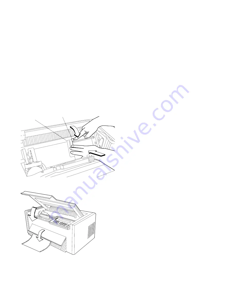
4. Close the right blue tractor door. Hold the tractor in place and

lock the blue locking lever.

Note:  If necessary, unlock the tractor and adjust it so that the
forms are not buckled or stretched too tightly.

Blue Tractor
Door

Blue Locking Lever

5. Close the access cover. Then close the paper door by pulling it

out and pushing it down until it latches.

1-28

User’s Guide 


Summary of Contents for 4230 - Model 4i3 B/W Dot-matrix Printer

Page 1: ...4230 Printer Models 101 1S2 201 2S2 4S3 and 5S3 User s Guide SA40 0593 04 ...

Page 2: ......

Page 3: ...4230 Printer Models 101 1S2 201 2S2 4S3 and 5S3 User s Guide SA40 0593 04 IBM ...

Page 4: ...he IBM Software Manufacturing Company at 1 800 879 2755 Outside the U S customers should contact the IBM branch office serving their locality A form for reader s comments is provided at the back of this publication If the form has been removed comments may be addressed to IBM Corporation Information Development Dept G60 1701 North Street Endicott NY 13760 5553 USA IBM may use or distribute whateve...

Page 5: ...oad Forms 1 24 Loading Forms in the F1 Forms Device 1 26 Using the Printer Verification Test for the F1 Forms Device 1 33 Adjusting the Print Quality 1 38 Adjusting the Tractor Tension 1 39 Adjusting the Forms Thickness Setting 1 40 Adjusting the Forms Tension 1 42 Adjusting the Left Margin 1 44 Adjusting the Top of Form Position 1 46 Adjusting the Print Alignment 1 48 Unloading Forms 1 51 Removin...

Page 6: ...usting the Left Margin 1 104 Adjusting the Top of Form Position 1 107 Adjusting the Print Alignment 1 109 Unloading Forms 1 113 Removing the Document Insertion Device F3 1 114 Using the Acoustic Cover 1 117 Removing the Acoustic Cover 1 117 Reinstalling the Acoustic Cover 1 117 Chapter 2 Attaching the 4230 Printer to Your Computer 2 1 Models 101 1S2 and 4S3 Twinaxial Attachment 2 2 Attaching a Twi...

Page 7: ...S2 and 4S3 3 12 Format Indicator Models 201 and 2S2 3 12 Format Online Indicator Model 5S3 3 13 Attention Indicator 3 13 Unit Check Indicator 3 14 Operator Panel Keys 3 14 Configuration Parameter Values 3 16 Operating States 3 17 Ready and Not Ready 3 17 Forms 3 18 Forms Handling Devices 3 19 Continuous Forms Device F1 3 19 Dual Purpose Forms Device F2 3 20 Document Insertion Device F3 3 21 Auto S...

Page 8: ...ng A 3 Customer Responsibility A 7 Appendix B Problem Solving B 1 Using the Status Code and Problem Listings B 2 Status Codes B 3 Problem List Index B 34 Forms Device Inspection B 35 Problem List B 38 Print Quality and Ribbon Problems B 44 Miscellaneous Problems B 47 Appendix C Forms Information C 1 Forms Specifications C 1 Continuous Forms F1 or F2 C 2 Cut Sheet Forms F3 C 3 Cut Sheet Forms F4 C ...

Page 9: ...E 1 Recommended Attachment Cables for PCs and Compatible Serial Ports E 2 Recommended Attachment Cables for AS 400 Workstation Controllers E 2 Cable Configurations E 3 RS 232C E 3 RS 422A E 5 IBM Parallel Attachment Models 4S3 and 5S3 E 6 Glossary X 1 Index X 9 Contents vii ...

Page 10: ...viii User s Guide ...

Page 11: ...censing IBM Corporation 208 Harbor Drive Stamford CT 06904 2501 USA Electronic Emission Notices Federal Communication Commission FCC Statement Note This equipment has been tested and found to comply with the limits for a Class A digital device pursuant to Part 15 of the FCC Rules These limits are designed to provide reasonable protection against harmful interference when the equipment is operated ...

Page 12: ...nt of Communications Operation in a residential area may cause unacceptable interference to radio and TV reception requiring the owner or operator to take whatever steps are necessary to correct the interference Avis de conformité aux normes du ministère des Communications du Canada Cet équipement ne dépasse pas les limites de Classe A d émission de bruits radioélectriques pour les appareils numér...

Page 13: ... Zealand Compliance Statement This is a Class A computing device and shall not be located at a distance closer than 20 meters from the boundary of a residential property Japanese VCCI Korean EMI Notices xi ...

Page 14: ...BM Corporation in the United States or other countries or both AFP AS 400 Application System 400 ES 9000 ES 9370 IBM and the IBM logo IPDS Intelligent Printer Data Stream OS 400 The following terms denoted by a double asterisk in this publication are trademarks of other companies as follows Lexmark Lexmark International Inc xii User s Guide ...

Page 15: ...risk of electric shock and personal injury Connect the machine only to a properly grounded outlet of the correct voltage The voltage your machine will accept is indicated on the machine Make sure the machine is turned Off O before you connect or disconnect the power cord or other cables If the machine has cables other than the power cord you must connect them before you plug the power cord into an...

Page 16: ...s Therefore replacement parts must have the identical or equivalent characteristics as the original parts The maintenance information for this machine has been written for the professional service person and is not intended to be used by others xiv User s Guide ...

Page 17: ...endix gives the experienced IBM 4230 Printer operator a guideline for teaching others how to use the printer How to Use This Guide The following list describes the contents of each chapter and the appendices in more detail Chapter 1 Setting Up the 4230 Printer provides information on setting up the 4230 Printer Chapter 2 Attaching the 4230 Printer to Your Computer provides information on connectin...

Page 18: ...face You will use the IBM 4230 Printer Models 101 1S2 201 2S2 4S3 and 5S3 User s Guide with the IBM 4230 Printer Models 101 1S2 201 2S2 4S3 and 5S3 Operator Panel Instructions Topics in the IBM 4230 Printer Models 101 1S2 201 2S2 4S3 and 5S3 Operator Panel Instructions include The operator panel Configuration options See Publications on page xvii for a complete list of publications Note If you pla...

Page 19: ...eference Guide SA40 0592 This card shows the key functions and the available configuration values and the process for setting them IBM 4230 Printer Planning and Site Preparation Guide GC40 1700 This guide contains detailed information to help you plan for and prepare the site for a 4230 Printer installation IBM 4230 Printer Models 101 1S2 201 2S2 4S3 and 5S3 Product and Programming Description GC4...

Page 20: ...d 4232 Printers IBM 4230 and 4232 Printers Maintenance Information Manual SA40 0572 This manual provides detailed maintenance procedures for the 4230 and 4232 Printers IBM 4230 and 4232 Printers Illustrated Parts Catalog SA40 0573 This parts catalog contains listings and illustrations of all replacement assemblies and detail parts for the 4230 and 4232 Printers IBM 4230 and 4232 Printers Safety In...

Page 21: ...ferent forms devices to move paper through the printer Each device does a different type of print job depending on the type of forms you use continuous forms for large printouts tear off forms such as retail invoices or cut sheet forms See Forms Handling Devices on page 3 19 for more information The 4230 Printer has four different print quality settings Fast Draft Quality DP Data Processing Qualit...

Page 22: ...o be printed per vertical inch 6 8 For more information see Using Print Format and Quality Parameters in IBM 4230 Printer Models 101 1S2 201 2S2 4S3 and 5S3 Operator Panel Instructions or Introducing the 4230 Printer in IBM 4230 Printer Models 101 1S2 201 2S2 4S3 and 5S3 Product and Programming Description xx User s Guide ...

Page 23: ... 201 2S2 4S3 and 5S3 Operator Panel Instructions Use this manual to learn how to have the printer perform each function available through the operator panel IBM 4230 Printer Models 101 1S2 and 4S3 Quick Reference Guide or IBM 4230 Printer Models 201 2S2 and 5S3 Quick Reference Guide Use the guide as a reference when operating the printer The guide should be posted near the printer If you are insta...

Page 24: ...es F3 Device Only Printer User s Guide Operator Panel Instructions Twinaxial Attached Printers Maintenance Manuals Notes a Contact your place of purchase if any of the items shown above are missing b The Document Insertion Device F3 is shipped with a long and short lower forms guide and a paper door If you ordered the F3 forms device be sure that you find the guides and paper door and set them asi...

Page 25: ...f the printer 3 Remove the protective film from the access cover window and discard it 4 Remove the packaging material if present from under the acoustic door 5 Open the access cover Then open the front paper door as follows a Pull the door up until it will not go any higher b Push the door back slightly to lock it in the open position A c c e s s C o v e r P a p e r D o o r Chapter 1 Setting Up t...

Page 26: ...6 Find the orange tie on the right side of the printer to the left of the print head Carefully cut the orange tie and remove it from the printer Orange Tie 1 4 User s Guide ...

Page 27: ... knob and orange shipping brace in the center of the printer Unscrew the knob and remove the knob and shipping brace from the printer S h i p p i n g B r a c e Note Save the shipping brace in case you relocate the printer Chapter 1 Setting Up the 4230 Printer 1 5 ...

Page 28: ... these steps 1 Slide the print head to the center of the printer 2 Remove the ribbon cartridge from the package 3 Remove the yellow clip from the ribbon 4 Turn the blue ribbon advance knob clockwise to take up slack in the ribbon If the ribbon does not move contact your place of purchase and replace the ribbon cartridge Remove Yellow Clip Blue Ribbon Advance Knob 1 6 User s Guide ...

Page 29: ...nob to align the slots Lower the ribbon cartridge onto the metal post Be sure that the plastic tab on the bottom of the ribbon cartridge aligns with the hole in the printer casting B l u e S l o t t e d O p e n i n g M e t a l P o s t T a b 6 Press the cartridge down firmly to snap it into place Chapter 1 Setting Up the 4230 Printer 1 7 ...

Page 30: ...bbon guide with the ribbon guide posts on the print head carrier Press the guide all the way down on the posts until the tops of the posts are even with the top of the ribbon guide Ribbon Guide Ribbon Guide Posts 1 8 User s Guide ...

Page 31: ...ide fits over the ribbon drive post but does not latch down b There are no twists or folds in the ribbon c The ribbon is not catching on the print head d The ribbon moves when you turn the blue ribbon advance knob clockwise If the ribbon does not move replace the ribbon cartridge B l u e R i b b o n A d v a n c e K n o b Chapter 1 Setting Up the 4230 Printer 1 9 ...

Page 32: ...s necessary It is the responsibility of the customer or the person installing the machine to connect it to a properly grounded outlet Seek professional assistance before using an adapter or extension cord such a device could interrupt the grounding circuit If this machine is connected to an outlet that has been incorrectly connected to the building wiring serious electric shock could result 1 Make...

Page 33: ...own in the following figure x x x x x x x x x x x x x x x x x x x x x x x x x x x x x x x x x x x x x x x x x x x x x x x x x x x x x x x x x x x x x x x x x x x x x x x x x x x x x x x x x x x x x x x x x x x x x x x x x x x x x x x x x x x x x x x x x x x x x To change the language shown on the operator panel display see Using Printer Setup Parameters in IBM 4230 Printer Models 101 1S2 201 2S2 4...

Page 34: ...cro M i cro Darker Lighter Quick M e n u Te st Scroll Scroll Enter Return Power Ready Processing Online Attention Unit Check Figure 1 1 4230 Printer Models 101 and 1S2 Operator Panel M e n u Load Eje ct F o rm Feed Start S et Top of Form Stop C ancel P r i n t Te s t Sc roll Sc roll M i c r o M i c r o L in e Feed D a rk er Li gh ter E nter R etu rn P o w e r Rea dy Pro c es sin g Atte ntion Unit ...

Page 35: ... I n t e r f a c e Figure 1 3 4230 Printer Model 4S3 Operator Panel P A 1 H e x P r i n t P A 2 D i s p l a y I n t e r f a c e M e n u L o a d E j e c t F o r m F e e d S t a r t S e t T o p o f F o r m S t o p C a n c e l P r i n t T e s t S c r o l l S c r o l l M i c r o M i c r o L i n e F e e d D a r k e r L i g h t e r E n t e r R e t u r n P o w e r R e a d y P r o c e s s i n g A t t e n ...

Page 36: ...he alarm beeps Then the printer displays The printer then displays b The print head and ribbon move c The printer displays and then followed by The Attention indicator also blinks and the alarm beeps This status code appears because forms have not been loaded DIAGNOSTICS IN PROGRESS A Calibrating Printer A Please Wait DIAGNOSTICS COMPLETE A ðð1 END OF FORMS LOAD FORMS 1 14 User s Guide ...

Page 37: ...ou may see Ignore these messages until you have attached the printer to your computer Press Stop to turn off the alarm if necessary 5 If the printer operated correctly go to Step 6 on page 1 17 otherwise check the following ð9ð COVER DOOR OPEN PRINT SPEED REDUCED ð15 COMMUNICATIONS CHECK CHECK CABLE ð28 COMMUNICATIONS CHECK CALL SYSTEM OPERATOR ð29 LINK ERROR Chapter 1 Setting Up the 4230 Printer ...

Page 38: ...Off O 2 Unplug the printer power cord from the electrical outlet 3 Be sure that the power cord is firmly connected to the rear of the printer 4 Try another electrical device such as a lamp in the outlet 5 If the outlet is working connect the printer to the outlet again Return to Step 4 on page 1 14 and try again 6 If the printer still fails to come on call your service representative b Did the pri...

Page 39: ...ll or Scroll until the printer displays 8 Press Enter to select this category 9 Press Scroll or Scroll until the printer displays 10 Press Enter to select this parameter 11 Press Scroll or Scroll until the printer displays the desired forms device 12 Press Enter to set the device An asterisk appears beside your choice of device 13 You now need to save this change to the power on custom set Custom ...

Page 40: ...ter displays e Press Enter to save the configuration changes The printer displays 14 Turn the power Off O CONFIGURATION MENU Printer Setup CONFIGURATION MENU Configuration Storage Configuration Storage Save Current Values Save Current Values Custom Set A Save Current Values Custom Set A Saved 1 18 User s Guide ...

Page 41: ...de the print head to the center of the printer 16 You are now ready to install the forms device Go to Selecting the Forms Device Installation Procedure on page 1 20 Chapter 1 Setting Up the 4230 Printer 1 19 ...

Page 42: ... install the F1 forms device Go to Installing and Using the Dual Purpose Forms Device F2 on page 1 55 to install the F2 forms device Go to Installing and Using the Document Insertion Device F3 on page 1 88 to install the F3 forms device See Setting Up Your 4230 Printer with ASF in IBM 4230 Printer Auto Sheet Feeder General Information to install the F4 forms device 1 20 User s Guide ...

Page 43: ...the F1 forms device follow these steps 1 Hold the forms device so that the device number F1 is in the upper left corner facing you Note the bottom metal bar and the clips they will be important later 2 Remove the orange shipping clip if installed Important The F1 forms device for the 4230 Printer has a circle around the F1 emblem Use only these forms devices in the 4230 Printer T o p o f F o r m s...

Page 44: ...ce until the device rests in the slots of the frame End of Device End of Device Slot in Frame Slot in Frame Top of Forms Device Platen Rod 4 Look through the front bottom opening in the printer and find the metal bar at the bottom of the forms device 5 Grasp the metal bar with BOTH hands and pull firmly toward you and then upward until both ends LOCK into place Bottom of Forms Device Metal Bar 1 2...

Page 45: ...gure and compare it to your printer Check both the left and right sides Are the clips around the platen rod as shown If so you installed the forms device correctly If not repeat Steps 3 through 5 P l a t e n R o d P l a t e n R o d C l i p C l i p Chapter 1 Setting Up the 4230 Printer 1 23 ...

Page 46: ...on knob by turning it counterclockwise and then move the blue forms tension knob towards the bottom of the printer until you see the below the number 1 Blue Forms Tension Knob Note Moving the blue forms tension knob to the position lets you load forms 3 Unlock the blue locking lever on the right tractor Slide the tractor to the extreme right Blue Locking Lever 1 24 User s Guide ...

Page 47: ...4 Open both of the blue tractor doors B l u e T r a c t o r D o o r s 5 Get continuous forms paper that is at least 203 2 mm 8 in wide Chapter 1 Setting Up the 4230 Printer 1 25 ...

Page 48: ...w these steps 1 Feed the form into the bottom front of the printer Be sure that the form goes under the blue forms guide forms sensor and between the tension plates See the figure on page 1 21 for help in locating the tension plates Blue Forms Guide Forms Sensor 1 26 User s Guide ...

Page 49: ...ctor pins Close the left blue tractor door B l u e T r a c t o r D o o r 3 Move the right tractor until the right paper holes of the form fit on the right tractor pins Be sure that the forms are straight T r a c t o r P i n s Chapter 1 Setting Up the 4230 Printer 1 27 ...

Page 50: ...ocking lever Note If necessary unlock the tractor and adjust it so that the forms are not buckled or stretched too tightly Blue Tractor Door Blue Locking Lever 5 Close the access cover Then close the paper door by pulling it out and pushing it down until it latches 1 28 User s Guide ...

Page 51: ...4S3 you may see or on Models 201 2S2 and 5S3 you may see While on Models 4S3 and 5S3 when parallel or serial is the active interface you may see Ignore these messages until you have attached the printer to your computer Press Stop to turn off the alarm if necessary NOT READY A ð15 COMMUNICATIONS CHECK CHECK CABLE ð28 COMMUNICATIONS CHECK CALL SYSTEM OPERATOR ð29 LINK ERROR Chapter 1 Setting Up the...

Page 52: ...ne d If you pressed Micro you might have slack in the forms Pull lightly downward on the forms at the bottom of the printer to remove the slack e Press Set Top of Form to establish the first print line Note The Set Top of Form key establishes the first line at which printing is to start on each form The alarm beeps each time you press the Set Top of Form key and the printer displays TOP OF FORM SE...

Page 53: ...ob upward to the number of form copies you are using Make sure you do not unlatch the forms device For example if you are using single part forms set the lever to 1 If you are using two part forms set the lever to 2 Tighten the blue forms tension knob by turning it clockwise Close the paper door by pulling it out and pushing it down until it latches B l u e F o r m s T e n s i o n K n o b Chapter ...

Page 54: ...e on Models 4S3 and 5S3 when parallel or serial is the active interface you may see Ignore these messages until you have attached the printer to your computer Press Stop to turn off the alarm if necessary READY A ð15 COMMUNICATIONS CHECK CHECK CABLE ð28 COMMUNICATIONS CHECK CALL SYSTEM OPERATOR ð29 LINK ERROR 1 32 User s Guide ...

Page 55: ...1S2 and 4S3 you may see or on Models 201 2S2 and 5S3 you may see While on Models 4S3 and 5S3 when parallel or serial is the active interface you may see Ignore these messages until you have attached the printer to your computer Press Stop to turn off the alarm if necessary 4 Press Test READY A NOT READY A ð15 COMMUNICATIONS CHECK CHECK CABLE ð28 COMMUNICATIONS CHECK CALL SYSTEM OPERATOR ð29 LINK E...

Page 56: ...for the printer to stop printing and the Ready indicator to go off 8 Press Form Feed until you can remove the printout The lines numbered 1 through 9 should print as shown on the sample printout on page 1 35 and the remainder of the printout should be clear and readable OPERATOR PRINT TESTS Printer Demonstration OPERATOR PRINT TESTS Printer Verification 1 34 User s Guide ...

Page 57: ...Chapter 1 Setting Up the 4230 Printer 1 35 ...

Page 58: ...ming or an incorrect printer verification printout Forms device Ribbon cartridge Forms Repeat the Setup Instructions from page 1 6 if you suspect a ribbon forms or forms device installation problem b Be sure that enough forms are loaded and press Enter or Start to get another printout c If the second printout is not similar to the sample printout go to Appendix B Problem Solving d Once you get a g...

Page 59: ...t Custom Set A factory defaults and save this printout for future reference You are ready to attach the printer to your computer Go to Chapter 2 Attaching the 4230 Printer to Your Computer on page 2 1 Note See pages 1 38 through 1 53 for making adjustments unloading forms and removing the forms device Chapter 1 Setting Up the 4230 Printer 1 37 ...

Page 60: ...ing is not correct it can be adjusted To adjust the forms thickness see Adjusting the Forms Thickness Setting on page 1 40 Note The Automatic Forms Thickness Adjustment AFTA mechanism automatically measures the forms thickness and adjusts the gap from the print head to the platen rod based on the measured value See Automatic Forms Thickness Adjustment AFTA on page 3 8 for information on how the 42...

Page 61: ... left paper holes of the forms on the tractor pins without stretching or tearing the holes To adjust the tractor tension on the F1 forms device follow these steps 1 Feed several forms through the printer 2 Observe the left and right paper holes of the forms If the paper holes are stretched or torn on the outside edges the tractor tension is too tight not enough buckle in the forms If the forms twi...

Page 62: ...rections to the distance if the print output is not as you desire It is up to you to decide if the print is dark or light enough to meet your requirements To adjust the forms thickness setting with the F1 forms device follow these steps 1 The forms thickness setting must be adjusted when the printer is printing or has printed and is ready Press Start if needed to have the printer display 2 To make...

Page 63: ...he print head relative to the limits As long as you press Darker or Lighter the printer displays an increasing amount of darkness or lightness until one of the limits of the gap is reached The printer displays either or As you adjust the gap you may also see the printer display This message tells you that the forms thickness setting is at the automatically set value LIGHT wwwwwwww DARK LIGHT wwwww...

Page 64: ...and allows forms to pass freely while loading The 1 setting puts the least amount of tension on the form Settings 2 through 6 vary the amount of tension on the form and approximately relate to the number of sheets in the form you use Set the tension lever to the number of sheets in the form being used Note Higher numbers are toward the top and lower numbers are toward the bottom of the printer Whe...

Page 65: ...re is too little tension on the forms If the tension is satisfactory continue to print Increasing Forms Tension To increase tension on the forms follow these steps 1 Loosen the blue forms tension knob by rotating the knob counterclockwise 2 Move the knob to a higher number setting For example if the knob was set at 2 move the knob to 3 3 Tighten the blue forms tension knob by rotating the knob clo...

Page 66: ... in from the center of the tractor pins for continuous forms and the left edge of a cut form To align the left margin position follow these steps 1 If the printer is ready press Stop The printer displays 2 Enter the Operator Print Tests by pressing Test The printer displays 3 Press Scroll or Scroll until the printer displays 4 Press Enter or Start to begin the test The printer displays where xxx i...

Page 67: ...o move the forms between printing the rows of H s 8 Press Stop or Cancel Print to exit the test Note If you want the new left margin position saved when you turn off the printer you must save it in a Custom Set See Storing Configuration Parameters in IBM 4230 Printer Models 101 1S2 201 2S2 4S3 and 5S3 Operator Panel Instructions for information on saving configurations You may also adjust the left...

Page 68: ...1 Pull the door up until it will not go any higher 2 Push the door back slightly to lock it in the open position Access Cover Paper Doo r Next load forms if necessary see Loading Forms in the F1 Forms Device on page 1 26 for more information Complete the following steps to make fine vertical adjustments to the top of form position To set the top of form position follow these steps 1 Press Stop The...

Page 69: ... of Form Alignment Test see Top of Form Alignment on page 5 4 to print a line of characters to determine more accurately where you have set the top of form position 3 When the form is in the correct position press Set Top of Form The alarm beeps and the printer displays 4 Advance the form by pressing Form Feed and decide if the form is on the desired line If necessary repeat Steps 1 through 4 of t...

Page 70: ...lays 2 Press Test The printer displays 3 Press Scroll or Scroll until the printer displays 4 Press Enter or Start to print this test The Ready indicator goes on and printing begins The test prints samples using alignment values higher and lower than the default value The print sample using the default value is indicated with an asterisk The alignment printout is complete when the Ready indicator g...

Page 71: ...The printer displays Bidirectional Adjustment Chapter 1 Setting Up the 4230 Printer 1 49 ...

Page 72: ...new default value The printer then prints another line to demonstrate the new default value and the test is complete or Press Stop to end the test without changing anything and return to the Operator Print Tests menu or Press Cancel Print to end the test exit test mode perform a partial reset and have the printer display Note See Chapter 5 Using the Operator Print Tests for more information READY ...

Page 73: ...ps 1 Press Stop The printer displays 2 Open the acoustic cover 3 Grasp the form below the printer and tear along the perforation 4 Press Form Feed as many times as needed to advance and remove the remaining form or forms NOT READY A Chapter 1 Setting Up the 4230 Printer 1 51 ...

Page 74: ...5 Remove the form or forms from the top of the printer Warning Do not remove forms by pulling them out from the bottom Damage to the forms device can result 1 52 User s Guide ...

Page 75: ... follow these steps 1 If forms are in the printer unload them see Unloading Forms on page 1 51 then continue with Step 2 of this procedure 2 Turn the power Off O 3 Open the access cover Then open the front paper door as follows a Pull the door up until it will not go any higher b Push the door back slightly to lock it in the open position A c c e s s C o v e r P a p e r D o o r Chapter 1 Setting U...

Page 76: ...at the bottom of the device toward the rear of the printer until the forms device unlocks Bottom of Forms Device Metal Bar 5 Grasp the top of the forms device and lift it out Top of Forms Device Platen Rod 1 54 User s Guide ...

Page 77: ...al Purpose Forms Device F2 To install the F2 forms device follow these steps 1 Hold the forms device so that the device number F2 is in the upper left corner facing you Note the bottom metal bar and the clips they will be important later Important The F2 forms device for the 4230 Printer has a box around the F2 emblem Use only these forms devices in the 4230 Printer B o t t o m M e t a l B a r C l...

Page 78: ...e into the printer behind the platen rod Be sure that F2 is in the upper left corner facing you and the blue tractor doors at the bottom of the device enter the printer first Align the ends of the device with the slots in the frame Continue to lower the device until the ends of the device rest in the slots of the frame End of Device End of Device Slot in Fram e Slot in Fram e Top of Form s Device ...

Page 79: ...ind the metal bar at the bottom of the forms device 5 Grasp the metal bar with BOTH hands and pull firmly toward you and then upward until both ends LOCK into place B o t t o m o f F o r m s D e v i c e M e t a l B a r Chapter 1 Setting Up the 4230 Printer 1 57 ...

Page 80: ...lowing figure and compare it to your printer Check both the left and right sides Are the clips around the platen rod as shown If so you installed the forms device correctly If not repeat Steps 3 on page 1 56 through 5 on page 1 57 Platen Rod Clip Platen Rod Clip 1 58 User s Guide ...

Page 81: ...s device follow these steps 1 Slide the print head to the far left side of the printer 2 Open both of the blue tractor doors B l u e T r a c t o r D o o r s 3 Get continuous forms paper that is at least 203 2 mm 8 in wide Chapter 1 Setting Up the 4230 Printer 1 59 ...

Page 82: ...01 1S2 and 4S3 you may see or on Models 201 2S2 and 5S3 you may see While on Models 4S3 and 5S3 when parallel or serial is the active interface you may see Ignore these messages until you have attached the printer to your computer Press Stop to turn off the alarm if necessary ðð1 END OF FORMS LOAD FORMS NOT READY A ð15 COMMUNICATIONS CHECK CHECK CABLE ð28 COMMUNICATIONS CHECK CALL SYSTEM OPERATOR ...

Page 83: ...each side Be sure that the form goes under the blue forms guide forms sensor B l u e F o r m s G u i d e F o r m s S e n s o r 5 Put the left paper holes over the left tractor pins Close the left blue tractor door B l u e T r a c t o r D o o r Chapter 1 Setting Up the 4230 Printer 1 61 ...

Page 84: ...e the right blue tractor door Right Tractor Assembly 7 Hold the right tractor in place and lock the blue locking lever Blue Locking Lever Right Tractor Blue Locking Lever Note If necessary unlock the tractor and adjust it so that the forms are not buckled or stretched too tightly Be sure that you lock the locking lever when you are finished adjusting 1 62 User s Guide ...

Page 85: ...rmation see Adjusting the Load Position on page 1 81 Note You can adjust the load position by using the Micro Micro or Line Feed keys If you plan to use the Document on Demand feature see Adjusting the Tear off Position on page 1 79 for more information a b c d e f P l a t e n R o d P l a t e n R o d P l a t e n R o d S u r f a c e F i r s t P r i n t L i n e Chapter 1 Setting Up the 4230 Printer ...

Page 86: ...ch printing is to start on each form The alarm beeps each time you press the Set Top of Form key and the printer displays 11 Close the access cover Then close the paper door by pulling it out and pushing it down until it latches Note If you load forms on the tractors before turning on the power the printer will automatically load forms to the load position TOP OF FORM SET 1 64 User s Guide ...

Page 87: ...1S2 and 4S3 you may see or on Models 201 2S2 and 5S3 you may see While on Models 4S3 and 5S3 when parallel or serial is the active interface you may see Ignore these messages until you have attached the printer to your computer Press Stop to turn off the alarm if necessary 4 Press Test READY A NOT READY A ð15 COMMUNICATIONS CHECK CHECK CABLE ð28 COMMUNICATIONS CHECK CALL SYSTEM OPERATOR ð29 LINK E...

Page 88: ...for the printer to stop printing and the Ready indicator to go off 8 Press Form Feed until you can remove the printout The lines numbered 1 through 9 should print as shown on the sample printout on page 1 67 and the remainder of the printout should be clear and readable OPERATOR PRINT TESTS Printer Demonstration OPERATOR PRINT TESTS Printer Verification 1 66 User s Guide ...

Page 89: ...Chapter 1 Setting Up the 4230 Printer 1 67 ...

Page 90: ...ng or an incorrect printer verification printout Forms device Ribbon cartridge Forms Repeat the Setup Instructions on page 1 6 if you suspect a ribbon forms or forms device installation problem b Be sure that enough forms are loaded and press Enter or Start to get another printout c If the second printout still is not similar to the sample printout go to Appendix B Problem Solving d Once you get a...

Page 91: ...t Custom Set A factory defaults and save this printout for future reference You are ready to attach the printer to your computer Go to Chapter 2 Attaching the 4230 Printer to Your Computer on page 2 1 Note See pages 1 70 through 1 86 for making adjustments unloading forms and removing the forms device Chapter 1 Setting Up the 4230 Printer 1 69 ...

Page 92: ...s thickness and adjust itself automatically However if this setting is not correct it can be adjusted To adjust the forms thickness see Adjusting the Forms Thickness Setting on page 1 73 Note The Automatic Forms Thickness Adjustment AFTA mechanism automatically measures the forms thickness and adjusts the gap from the print head to the platen rod based on the measured value See Automatic Forms Thi...

Page 93: ...ension The tractor tension adjustment controls the amount of buckle that the forms have when they are loaded in the printer Since the left tractor does not move you make this adjustment by moving the right tractor The ideal adjustment is to center the right and left paper holes of the forms on the tractor pins without stretching or tearing the holes To adjust the tractor tension on the F2 forms de...

Page 94: ...ard the left side of the printer to loosen the tension on the forms Unlock and move the tractor toward the right side of the printer to tighten the tension on the forms Left Margin Left Margin Right Margin Right Margin Correct Incorrect 4 Lock the tractor 1 72 User s Guide ...

Page 95: ...ing with the F2 forms device follow these steps 1 The forms thickness setting must be adjusted when the printer is printing or has printed and is ready Press Start if needed to have the printer display 2 To make the print darker press Darker The printer displays The print head moves closer to the paper and the print becomes darker Note The print may not get darker if the ribbon is worn or if there...

Page 96: ...is reached The printer displays either or As you adjust the gap you may also see the printer display This message tells you that the forms thickness setting is at the automatically set value See Understanding the Operator Panel in IBM 4230 Printer Models 101 1S2 201 2S2 4S3 and 5S3 Operator Panel Instructions for more information on this setting LIGHT wwwwwwwwwwwwwwwwwww DARK DARKNESS LIMIT REACHE...

Page 97: ...center of the tractor pins for continuous forms and the left edge of a cut form To align the left margin position follow these steps 1 If the printer is ready press Stop The printer displays 2 Enter the Operator Print Tests by pressing Test The printer displays 3 Press Scroll or Scroll until the printer displays 4 Press Enter or Start to begin the test The printer displays where xxx is the current...

Page 98: ...r Form Feed to move the forms between printing the rows of H s 8 Press Stop or Cancel Print to exit the test Note If you want the new left margin position saved when you turn off the printer you must save it in a Custom Set See Storing Configuration Parameters in IBM 4230 Printer Models 101 1S2 201 2S2 4S3 and 5S3 Operator Panel Instructions for information on saving configurations You may also ad...

Page 99: ...pen the front paper door as follows 1 Pull the door up until it will not go any higher 2 Push the door back slightly to lock it in the open position A c c e s s C o v e r P a p e r D o o r Next load forms if necessary see Loading Forms in the F2 Forms Device on page 1 60 for more information Complete the following steps to make fine vertical adjustments to the top of form position To set the top o...

Page 100: ...accurately where you have set the top of form position 3 When the form is in the correct position press Set Top of Form The alarm beeps and the printer displays 4 Advance the form by pressing Form Feed and decide if the form is on the desired line If necessary repeat Steps 1 through 4 of this procedure until the top of form position is correctly aligned 5 If you plan to use the Document on Demand ...

Page 101: ...cator goes off The paper quickly advances to the tear off position If you have Models 4S3 and 5S3 you can also use the Automatic Eject or Automatic Restore options to change the tear off position of a form See IBM 4230 Printer Models 101 1S2 201 2S2 4S3 and 5S3 Operator Panel Instructions for more information on these options 2 Open the acoustic cover 3 If the perforation on the form is not at the...

Page 102: ...or the printer displays and pressing Load Eject ejects the paper To remove the form follow these steps 1 Tear off the paper toward the front of the printer 2 Press Load Eject to position the next form back to the top of form position The Ready indicator comes on and you are ready to print the next print job ðð1 END OF FORMS LOAD FORMS 1 80 User s Guide ...

Page 103: ...the load position consistent with the top of form position Pressing Set Top of Form establishes the first print line at which printing is to start on each form The alarm beeps and the printer displays TOP OF FORM SET Adjusting the Print Alignment You can adjust dot registration and print quality for characters created using bidirectional printing The bidirectional alignment may need periodic adjus...

Page 104: ...oes on and printing begins The test prints samples using alignment values higher and lower than the default value The print sample using the default value is indicated with an asterisk The alignment printout is complete when the Ready indicator goes off OPERATOR PRINT TESTS Bidirectional Adjustment 1 82 User s Guide ...

Page 105: ...lue The printer then prints another line to demonstrate the new default value and the test is complete or Press Stop to end the test without changing anything and return to the Operator Print Tests menu or Press Cancel Print to end the test exit test mode perform a partial reset and have the printer display Note See Chapter 5 Using the Operator Print Tests for more information Bidirectional Adjust...

Page 106: ...e forms at the tear bar See Adjusting the Tear off Position on page 1 79 for the procedure 3 Press Stop The printer displays 4 Open the front paper door as follows a Pull the door up until it will not go any higher b Push the door back slightly to lock it in the open position Paper Door NOT READY A 1 84 User s Guide ...

Page 107: ...5 Open both of the blue tractor doors B l u e T r a c t o r D o o r s 6 Lift the form off the tractor pins and pull the form out from the bottom of the printer Chapter 1 Setting Up the 4230 Printer 1 85 ...

Page 108: ...e the F2 forms device follow these steps 1 If forms are in the printer unload them see Unloading Forms on page 1 84 then continue with Step 2 of this procedure 2 Turn the power Off O 3 Open the access cover Then open the front paper door as follows a Pull the door up until it will not go any higher b Push the door back slightly to lock it in the open position Access Cover Paper Door 1 86 User s Gu...

Page 109: ...ottom of the device toward the rear of the printer until the forms device unlocks B o t t o m o f F o r m s D e v i c e M e t a l B a r 6 Grasp the top of the forms device and lift it out T o p o f F o r m s D e v i c e Chapter 1 Setting Up the 4230 Printer 1 87 ...

Page 110: ...orms Device Installation on page 1 10 for the exact steps Installing the Document Insertion Device F3 To install the F3 forms device follow these steps 1 Hold the forms device so that the device number F3 is in the upper left corner facing you Note the bottom of the device the finger grips and the clips they will be important later F 3 F3 Clips Top of Forms Device Bottom of Forms Device Finger Gri...

Page 111: ...eft corner facing you The finger grips should be at the bottom and should enter the printer first Lower the device into the printer behind the platen rod and align the ends of the device with the slots in the frame Continue to lower the device until the ends of the device rest in the slots of the frame E n d o f D e v i c e E n d o f D e v i c e S l o t i n F r a m e S l o t i n F r a m e T o p o ...

Page 112: ...ard until both ends LOCK into place Finger Grips 6 To be sure that you have installed the forms device correctly look at the following figure and compare it to your printer Check both the left and right sides Are the clips around the platen rod as shown If so you installed the forms device correctly If not repeat Steps 3 on page 1 89 through 5 Platen Rod Platen Rod C lip C lip 1 90 User s Guide ...

Page 113: ...evice your shipment includes an F3 forms device paper door To change paper doors follow these steps 1 Open the standard paper door to the position shown Press the two tabs to release the door and slowly pull the door toward you Remove the standard paper door T a b S l o t P a p e r D o o r H i n g e P in s Chapter 1 Setting Up the 4230 Printer 1 91 ...

Page 114: ...es at the top of the door with the hinge pins on each side of the printer Be sure that you align the door at the angle shown Then slowly push the door in place F3 Paper Door Tab Slot Hinge Pin The F3 paper door locks in the open position similar to the standard door 1 92 User s Guide ...

Page 115: ...lled a Place the lower forms guide in front of the forms chute so that the tab is under the chute T a b C h u t e b Align the lower forms guide beside the blue forms guide forms sensor Then slide the lower forms guide to the left until it locks on 2 Get cut forms that are at least 203 2 by 279 4 mm 8 by 11 in Chapter 1 Setting Up the 4230 Printer 1 93 ...

Page 116: ...and against the left stop Unlock the blue locking lever and move the right roller assembly so that the pointer lines up with the right edge of the form Blue Locking Lever Left Stop Left Stop Upper Forms Guide Pointer Right Roller Assembly If needed use the white writing surface near the blue sliding guides to make pencil marks to help you line up the form 1 94 User s Guide ...

Page 117: ... L e v e r 3 Center the blue sliding guide between the roller assemblies B l u e S l i d i n g G u i d e 4 Close the access cover Then close the paper door by pulling it out and pushing it down until it latches Chapter 1 Setting Up the 4230 Printer 1 95 ...

Page 118: ... Models 101 1S2 and 4S3 you may see or on Models 201 2S2 and 5S3 you may see While on Models 4S3 and 5S3 when parallel or serial is the active interface you may see Ignore these messages until you have attached the printer to your computer Press Stop to turn off the alarm if necessary 4 Press Test READY A NOT READY A ð15 COMMUNICATIONS CHECK CHECK CABLE ð28 COMMUNICATIONS CHECK CALL SYSTEM OPERATO...

Page 119: ...e left edge of the lower forms guide to help feed the form in straight Feed the form until the top edge touches both the left and right feed rollers Continue to hold the form L o w e r F o r m s G u i d e The printer displays OPERATOR PRINT TESTS Printer Demonstration OPERATOR PRINT TESTS Printer Verification ð13 DATA TO PRINT LOAD FORMS ðð4 PRESS LOAD Chapter 1 Setting Up the 4230 Printer 1 97 ...

Page 120: ...he Ready indicator comes on and printing begins 9 Wait for the printer to stop printing and the Ready indicator to go off 10 The lines numbered 1 through 9 should print as shown on the sample printout and the remainder of the printout should be clear and readable 1 98 User s Guide ...

Page 121: ...ct printer verification printout Forms device Ribbon cartridge Forms Repeat the Setup Instructions from page 1 6 if you suspect a ribbon forms or forms device installation problem b Press Enter or Start load another form and press Load Eject to get another printout c If the second printout is still not similar to the sample printout go to Appendix B Problem Solving d Once you get a good printout g...

Page 122: ...n custom set Custom Set A factory defaults and save this printout for future reference You are ready to attach the printer to your computer Go to Chapter 2 Attaching the 4230 Printer to Your Computer on page 2 1 Note See pages 1 101 through 1 114 for making adjustments unloading forms and removing the forms device 1 100 User s Guide ...

Page 123: ...A mechanism automatically measures the forms thickness and adjusts the gap from the print head to the platen rod based on the measured value See Automatic Forms Thickness Adjustment AFTA on page 3 8 for information on how the 4230 Printer sets the forms thickness Left Margin and Top of Form Position The adjustment of the first print position can affect the appearance of the output especially if yo...

Page 124: ...ickness setting with the F3 forms device follow these steps 1 The forms thickness setting must be adjusted when the printer is printing or has printed and is ready Press Start if needed to have the printer display 2 To make the print darker press Darker The printer displays The print head moves closer to the paper and the print becomes darker Note The print may not get darker if the ribbon is worn...

Page 125: ...he printer displays either or As you adjust the gap you may also see the printer display This message tells you that the forms thickness setting is at the automatically set value See Understanding the Operator Panel in IBM 4230 Printer Models 101 1S2 201 2S2 4S3 and 5S3 Operator Panel Instructions for more information on this setting LIGHT wwwwwwwwwwwwwwwwwww DARK DARKNESS LIMIT REACHED LIGHT w DA...

Page 126: ...starting at 1 27 mm 0 05 in from the center of the tractor pins for continuous forms and from the left edge of a cut form To align the left margin position follow these steps 1 If the printer is ready press Stop The printer displays 2 Enter the Operator Print Tests by pressing Test The printer displays 3 Press Scroll or Scroll until the printer displays 4 Press Enter or Start to begin the test The...

Page 127: ...the form until the top edge touches both the left and right feed rollers Continue to hold the form L o w e r F o r m s G u i d e The printer displays 6 Press Load Eject The printer then displays where xxx is the current value of the left margin position ðð4 PRESS LOAD Left Margin Position xxx Chapter 1 Setting Up the 4230 Printer 1 105 ...

Page 128: ...Load Eject to move the forms between printing the rows of H s 10 Press Stop or Cancel Print to exit the test Note If you want the new left margin position saved when you turn off the printer you must save it in a Custom Set See Storing Configuration Parameters in IBM 4230 Printer Models 101 1S2 201 2S2 4S3 and 5S3 Operator Panel Instructions for information on saving configurations You may also ad...

Page 129: ...ft and right feed rollers Continue to hold the form L o w e r F o r m s G u i d e 2 Press Load Eject As the printer begins to pull in the form release the form The form loads to the top of form position 3 If the first print line is not where you want it to be press Micro Micro or Line Feed until it reaches the desired line Note If you need to adjust the paper downward adjust at least five steps be...

Page 130: ...m position adjustment from the default position is 101 6 and 8 47 mm 4 and 0 34 in 5 Press Load Eject to eject the form 6 Repeat Steps 1 and 2 on page 1 107 and decide if the form is loading to the desired position If necessary repeat this procedure again until the top of form position is correctly aligned TOP OF FORM SET 1 108 User s Guide ...

Page 131: ...the bidirectional alignment follow these steps 1 If the printer is ready press Stop The printer displays 2 Press Test The printer displays 3 Press Scroll or Scroll until the printer displays 4 Press Enter or Start to begin this test The printer displays NOT READY A OPERATOR PRINT TESTS Printer Demonstration OPERATOR PRINT TESTS Bidirectional Adjustment ð13 DATA TO PRINT LOAD FORMS Chapter 1 Settin...

Page 132: ... form Lower Forms Guide The printer displays 6 Press Load Eject As the printer begins to pull in the form release the form The Ready indicator goes on and printing begins The test prints samples using alignment values higher and lower than the default value The print sample using the default value is indicated with an asterisk The alignment printout is complete when the Ready indicator goes off ðð...

Page 133: ...The printer displays Bidirectional Adjustment Chapter 1 Setting Up the 4230 Printer 1 111 ...

Page 134: ...ue The printer then prints another line to demonstrate the new default you will need to load another form and the test is complete or Press Stop to end the test without changing anything and return to the Operator Print Tests menu or Press Cancel Print to end the test exit test mode perform a partial reset and have the printer display Note See Chapter 5 Using the Operator Print Tests for more info...

Page 135: ...Unloading Forms To unload forms from the F3 forms device 1 Press Load Eject 2 Open the acoustic cover 3 Remove the form from the top of the printer Chapter 1 Setting Up the 4230 Printer 1 113 ...

Page 136: ... the F3 forms device follow these steps 1 If forms are in the printer unload them see Unloading Forms on page 1 113 then continue with Step 2 of this procedure 2 Turn the power Off O 3 Open the access cover Then open the front paper door as follows a Pull the door up until it will not go any higher b Push the door back slightly to lock it in the open position Access Cover Paper Door 1 114 User s G...

Page 137: ...e device toward the rear of the printer until it unlocks F i n g e r G r i p s 5 Grasp the top of the forms device and lift it out P l a t e n R o d T o p o f F o r m s D e v i c e Chapter 1 Setting Up the 4230 Printer 1 115 ...

Page 138: ...t off the blue forms guide forms sensor Be sure that the tab clears the bottom of the chute before pulling the lower forms guide away from the printer Store the lower forms guide with your F3 forms device 7 If you are removing the F3 forms device to install a different forms device remove the F3 front paper door and install the standard front paper door 1 116 User s Guide ...

Page 139: ...s vertical 2 Locate the latch release tabs on both brackets 3 Depress the latch tabs while lifting the acoustic cover Reinstalling the Acoustic Cover To reinstall the acoustic cover over the paper exit area follow these steps Note The figure in this section shows the rear of the printer 1 Locate the slots near the paper exit area of the access cover R e a r V i e w B r a c k e t B r a c k e t S l ...

Page 140: ...over and insert them into the slots until they latch securely Paper Exit Area Latched Position Latched Position Latch Latch Bracket Bracket Rear View 3 Pivot the acoustic cover until it is closed over the paper exit area 1 118 User s Guide ...

Page 141: ...d coaxial connectors For Models 4S3 and 5S3 you may want to attach the printer to more than one computer If so you need to perform the steps in each appropriate section For Coaxial or Twinaxial look at the bezel at the rear of the printer If your printer has a feature card number or card name of Models 101 1S2 and 4S3 Twinaxial go to Models 101 1S2 and 4S3 Twinaxial Attachment on page 2 2 Models 2...

Page 142: ...s 0 go to Step 3 on page 2 4 If your desired printer address is not 0 see the following table for the valid values and follow Steps 1a on page 2 3 through 1g on page 2 4 to change the value If you do not know what to assign for the printer address check with your system operator If Desired Address Is Set Shown when Setting Printer Address 0 000 Printer Address 0 1 001 Printer Address 1 2 002 Print...

Page 143: ...d an error message displays b Press Stop The printer displays c Press Menu Then press Scroll or Scroll until the printer displays d Press Enter The printer displays DIAGNOSTICS IN PROGRESS A DIAGNOSTICS COMPLETE A ð15 COMMUNICATIONS CHECK CHECK CABLE CONFIGURATION MENU Printer Address Printer Address ððð Chapter 2 Attaching the 4230 Printer to Your Computer 2 3 ...

Page 144: ...t or disconnect the power cord or other cables If the machine has cables other than the power cord you must connect them before you plug the power cord into an outlet You must first unplug the power cord from the outlet when you remove the other cables Before you connect the cable to the V connector slip a cable shield over the end of the cable If you are connecting two cables slip a cable shield ...

Page 145: ...e with the two holes and the key in the end of the V connector For Models 101 and 1S2 Plug the signal cable into the following connector For Model 4S3 Plug the signal cable into the following connector Chapter 2 Attaching the 4230 Printer to Your Computer 2 5 ...

Page 146: ...of the connector You can connect another device to the unused end of the connector b The V connectors are self terminating and do not require you to set a terminator switch which might be found on other printer products 5 For Models 101 and 1S2 Turn the cable connector clockwise until it locks into place 2 6 User s Guide ...

Page 147: ...6 For Model 4S3 Turn the cable connector clockwise until it locks into place Chapter 2 Attaching the 4230 Printer to Your Computer 2 7 ...

Page 148: ...ug in the connector Turn the connector clockwise until it locks into place 8 For Model 4S3 Insert the cable connector into the printer connector on the bezel Make sure the cable connector is securely seated into place Push and fasten the top and bottom clips onto the cable connector Cable Connector Bezel Models 4S3 Models 101 and 1S2 2 8 User s Guide ...

Page 149: ...4S3 Place the two cables from the V connector through the cable clamp Make sure the cables lay flat and are not crossed M o d e l s 4 S 3 C a b l e C l a m p Chapter 2 Attaching the 4230 Printer to Your Computer 2 9 ...

Page 150: ...lays and Note If the printer does not show the correct display sequence go to the status code section of Appendix B Problem Solving 12 You no longer need to get access to the rear of the printer Position the printer so that the front edge aligns with the front edge of your printer stand or table DIAGNOSTICS IN PROGRESS A DIAGNOSTICS COMPLETE A READY A 2 10 User s Guide ...

Page 151: ...00 on page 2 12 for information about configuring your system If you are attaching your printer to an IBM System 36 go to Connecting Your Printer to an IBM System 36 on page 2 15 For all other computers see the appropriate instructions included with your computer for attaching the other end of the signal cable to your computer Chapter 2 Attaching the 4230 Printer to Your Computer 2 11 ...

Page 152: ... the 4230 Printer for instructions on loading and lining up forms in your printer 3 Ask the system supervisor if the cable from the printer to the host computer is installed CAUTION Make sure the machine is turned Off O before you connect or disconnect the power cord or other cables If the machine has cables other than the power cord you must connect them before you plug the power cord into an out...

Page 153: ... or No for Models 101 1S2 201 and 2S2 or Host Emulation Mode can be 4224 or 4230 for Models 4S3 and 5S3 use the parameters given in the following table Type your choices and press Enter Parameter Description Parameter Parameter Setting Device description DEVD Workstation printer name Device class DEVCLS LCL Device type TYPE 4214 Device model MODEL 2 Advance Function AFP NO Port number Printing POR...

Page 154: ...choices and press Enter Parameter Description Parameter Parameter Setting Device description DEVD Workstation printer name Device class DEVCLS RMT Device type TYPE 4214 Device model MODEL 2 Advanced Function AFP NO Location Address LOCADR xx Online at IPL ONLINE YES Attached controller CTL Twinaxial workstation controller name Form feed FORMFEED CONT 2 14 User s Guide ...

Page 155: ...etting Up the 4230 Printer for instructions on loading and lining up forms in your printer 3 Ask the system supervisor if the cable from the printer to the host computer is installed If the cable between the printer and host computer is installed go to Step 4 CAUTION Make sure the machine is turned Off O before you connect or disconnect the power cord or other cables If the machine has cables othe...

Page 156: ...n for the 4230 Printer see Adding or Deleting Local Display Stations and Printers and Adding or Deleting Remote Work Stations in Changing Your System Configuration SC21 9082 The printer can be used as a local or remote 4214 Model 2 printer Use the EA device code 4214 Model 2 Printer Device Code There is no specific 4230 device code If the printer is to be used as a remote printer it can be configu...

Page 157: ...l Signal Cable to the Printer CAUTION Make sure the machine is turned Off O before you connect or disconnect the power cord or other cables If the machine has cables other than the power cord you must connect them before you plug the power cord into an outlet You must first unplug the power cord from the outlet when you remove the other cables Chapter 2 Attaching the 4230 Printer to Your Computer ...

Page 158: ...rinter follow these steps 1 Attach one end of the signal cable to the cable connector at the rear of the printer 2 Turn the cable connector clockwise until the cable locks in place Bezel Models 201 and 2S2 Model 5S3 Cable Connector 2 18 User s Guide ...

Page 159: ... the printer does not show the correct display sequence go to the status code section of Appendix B Problem Solving 5 You no longer need to get access to the rear of the printer Position the printer so that the front edge aligns with the front edge of your printer stand or table DIAGNOSTICS IN PROGRESS A DIAGNOSTICS COMPLETE A READY A Chapter 2 Attaching the 4230 Printer to Your Computer 2 19 ...

Page 160: ...e provides the information you need to purchase the correct cable Interface Part Name Part Number Cable Length Parallel Parallel Cable 1525612 1 8 m 6 ft Serial RS 232C Serial Cable 8509386 6 m 20 ft Serial RS 422A Serial Cable 70X8652 15 2 m 50 ft Attaching a Parallel Cable CAUTION Make sure the machine is turned Off O before you connect or disconnect the power cord or other cables If the machine...

Page 161: ...pter cable 3 Then attach the parallel interface cable to the end of the adapter cable 4 Push the clips at each end of the connector into the notches on the parallel cable A d a p t e r C a b l e I B M p a r t n u m b e r 0 4 H 5 0 5 3 P a r a l l e l I n t e r f a c e C a b l e 5 Connect the power cord to the printer and to the electrical outlet Chapter 2 Attaching the 4230 Printer to Your Compute...

Page 162: ...status code section of Appendix B Problem Solving 7 You no longer need to have access to the rear of the printer Position the printer so that the front edge aligns with the front edge of your printer stand or table 8 Refer to your computer system documentation for information on attaching the cable to your computer DIAGNOSTICS IN PROGRESS A DIAGNOSTICS COMPLETE A READY A 2 22 User s Guide ...

Page 163: ...ord you must connect them before you plug the power cord into an outlet You must first unplug the power cord from the outlet when you remove the other cables To attach a serial cable 1 Attach the serial interface cable by pushing the connector into the printer port 2 Tighten the two locking screws to hold the cable in place Chapter 2 Attaching the 4230 Printer to Your Computer 2 23 ...

Page 164: ...correct display sequence go to the status code section of Appendix B Problem Solving 5 You no longer need to have access to the rear of the printer Position the printer so that the front edge aligns with the front edge of your printer stand or table 6 Refer to your computer system documentation for information on attaching the cable to your computer DIAGNOSTICS IN PROGRESS A DIAGNOSTICS COMPLETE A...

Page 165: ...IBM 4230 Printer It describes the various parts of your printer and shows you their locations This chapter also includes general information about the different forms devices that are available and instructions about caring for your new printer Copyright IBM Corp 1991 1994 3 1 ...

Page 166: ...e F orm s Sen so r u n de r p a p er d o o r Model Identification Figure 3 1 is an enlargement of a plate on the bottom front area of the printer TYPE 4230 XXX Serial Number S N XX XXXXX Model Number Figure 3 1 4230 Printer Model Identification Plate Record the model and serial numbers of your printer You will need this information as you use this and other 4230 Printer manuals 3 2 User s Guide ...

Page 167: ... wait 10 seconds after turning the power from Off O to On 3 Anytime you turn the power On you should verify the top of form position before running a job See Chapter 1 Setting Up the 4230 Printer for adjusting the top of form position for your forms device Warning If you turn the power Off O while data is in the printer buffer a temporary storage area or coming from the computer to the printer you...

Page 168: ...nds from these movements If no paper is loaded the printer displays Next the printer displays 6 Finally the printer displays the message Note If the power on test stops at any point or the printer displays a three digit code and error message before the test is complete a power on error has occurred If you have not loaded any forms or the printer is not communicating with the host the printer may ...

Page 169: ...bar Access Cover Opening the access cover Gives you access to the top of the printer for Cleaning Changing ribbon cartridges Loading or changing forms devices Causes printing and forms movement to slow down Note The printer may also display status code 090 See Status Codes on page B 3 for more information Front Paper Door Opening the front paper door Gives you access to the front area of the print...

Page 170: ...al Purpose Forms Device F2 installed the sensor works as A forms guide for aligning the left edge of the form A forms sensor for detecting the last form fed past it The printer stops printing after it prints the last line on the last form A forms sensor for detecting the presence of a form and activating the Load Eject key for the Automatic Load feature with the Dual Purpose Forms Device F2 A pape...

Page 171: ...s guide that fits over the sensor L o w e r F o r m s G u i d e The lower forms guide works as A guide for aligning the cut sheet form The sensor works as A sensor for detecting the presence of a form and activating the Load Eject key Chapter 3 Getting to Know Your Printer 3 7 ...

Page 172: ...press Stop and then Start For the Auto Sheet Feeder Device F4 AFTA measures the first sheet of each bin after you turn the printer On and after you press Stop and then Start The operator may adjust the AFTA by pressing Darker and Lighter Locate the information on your forms device and follow the procedure for adjusting the print darkness in Chapter 1 Setting Up the 4230 Printer Platen Rod The plat...

Page 173: ...c k M e n u T e s t S c r o l l S c r o l l E n t e r R e t u r n P o w e r R e a d y P r o c e s s i n g O n l i n e A t t e n t i o n U n i t C h e c k Figure 3 2 4230 Printer Models 101 and 1S2 Operator Panel M e n u L o a d E j e c t F o r m F e e d S t a r t S e t T o p o f F o r m S t o p C a n c e l P r i n t T e s t S c r o l l S c r o l l M i c r o M i c r o L i n e F e e d D a r k e r L ...

Page 174: ... st Scroll Scroll M i c r o M i c r o Line Feed Darker Lighter Enter Return Power Ready Processing Attention Unit Check Quick Format Online Figure 3 5 4230 Printer Model 5S3 Operator Panel This section describes each part of the operator panel For a detailed description on using the operator panel see IBM 4230 Printer Models 101 1S2 201 2S2 4S3 and 5S3 Operator Panel Instructions IBM 4230 Printer ...

Page 175: ...essages status codes and information error codes and messages and Configuration and Operator Print Tests Menus Status information helps you identify a problem or a normal condition that requires some action on your part For help with See Understanding status and error codes Using the Status Code and Problem Listings on page B 2 Using the Configuration Menu Checking and Changing Configuration Param...

Page 176: ...Indicator Models 101 1S2 and 4S3 The Online indicator has two operating conditions On The printer is communicating with the computer Off The printer is not communicating with the computer Format Indicator Models 201 and 2S2 The Format indicator has two operating conditions On The Cancel Print PA1 and PA2 keys are available for use that is you can press them in the printer s current state Off The P...

Page 177: ...y is only available when running an Operator Print Test The PA1 and PA2 keys are used to send special operator requests See Understanding the Operator Panel in the IBM 4230 Printer Models 101 1S2 201 2S2 4S3 and 5S3 Operator Panel Instructions for more information on these keys Attention Indicator The Attention indicator has two operating conditions Off The printer has not detected any conditions ...

Page 178: ...splays a status code go to Using the Status Code and Problem Listings on page B 2 Operator Panel Keys The operator panel has the following keys Menu Adjustment Group Darker Enter Lighter Return Menu Micro Scroll Micro Scroll Quick Reference Operation Group Cancel Print Form Feed Line Feed Load Eject Set Top of Form Start Stop Test Models 101 and 1S2 Display Address Hex Print Model 4S3 Display Inte...

Page 179: ... PA1 Hex Print PA2 Display Interface For a detailed description of each key see Understanding the Operator Panel in IBM 4230 Printer Models 101 1S2 201 2S2 4S3 and 5S3 Operator Panel Instructions Chapter 3 Getting to Know Your Printer 3 15 ...

Page 180: ...efault Set In other words all configuration changes are online only changes until they are saved using the Save Current Values parameter in the Configuration Menu under Configuration Storage For detailed information on saving configuration changes see Storing Configuration Parameters in IBM 4230 Printer Models 101 1S2 201 2S2 4S3 and 5S3 Operator Panel Instructions Some of the values you can chang...

Page 181: ...n test mode Operator Print Tests For the Models 101 1S2 and 4S3 the Online indicator is Off Ready and Not Ready Ready The printer is ready when you press Start and there are no error conditions The printer can be ready and online or offline Ready is indicated when the Ready indicator is On See Ready Indicator on page 3 12 for more information The printer displays unless an information message over...

Page 182: ...led torn or wrinkled forms When you use forms directly from a box remove the box tops or preferably remove the forms from the box Rough box top edges can damage the forms or cause the forms to jam All multiple part cut forms must be glued at the top edge A maximum of four part forms is recommended for the best registration feeding and stacking You might be able to use five or six part forms but te...

Page 183: ...p s F 1 T e n s i o n e r P l a t e s The Continuous Forms Device F1 is available for all models The device has an F1 surrounded by a circle in the upper left corner of the device Use this device when you are printing large volume work especially with very thin forms or work that requires minimum operator intervention See Installing and Using the Continuous Forms Device F1 on page 1 21 for informa...

Page 184: ...ork that requires you to separate the continuous forms between transactions and for most general printing requirements on continuous forms Use the tear bar to separate the printed forms Also the automatic loading feature autoload is enabled for this device See Installing and Using the Dual Purpose Forms Device F2 on page 1 55 for information on installing and removing the forms device loading and ...

Page 185: ...ls The device has an F3 by itself in the upper left corner of the device Use this device for printing cut forms for correspondence individual invoice forms and so on See Installing and Using the Document Insertion Device F3 on page 1 88 for information on installing and removing the forms device loading and unloading forms and adjusting the device Chapter 3 Getting to Know Your Printer 3 21 ...

Page 186: ... forms It can feed paper from one of three bins or a manual insertion slot The Auto Sheet Feeder Device F4 consists of two parts 1 a forms transport device shown above that mounts inside your printer and 2 a sheet feeder that sits in front of the printer on the same table See Setting Up Your 4230 Printer with ASF in IBM 4230 Printer Auto Sheet Feeder General Information for information on setting ...

Page 187: ... The print head is bidirectional prints left to right and right to left If there is a problem with the print head contact your IBM service representative Problem Determination Appendix B Problem Solving has codes and problem information The most probable cause of a printer problem is listed first There is also an inspection procedure for the forms devices to help you find and remove paper jams If ...

Page 188: ...ss cover closed except when replacing the ribbon or changing the forms Do not let objects rubber bands paper clips and so on drop into the printer Do not block the air vents on the printer sides Obstructions could restrict airflow and cause the printer to overheat Clean or vacuum the printer as necessary to remove dust or lint from the forms feed path Be sure that the power switch is turned Off O ...

Page 189: ...IBM 4230 Printer Auto Sheet Feeder General Information for information on using the Auto Sheet Feeder 3 Be sure that the parameter values agree with the application you are to print See the procedures for setting your parameter values in IBM 4230 Printer Models 101 1S2 201 2S2 4S3 and 5S3 Operator Panel Instructions 4 Load forms When you load forms be sure that you use the correct forms loading pr...

Page 190: ...the printed results do not appear the way you expect Stopping or Canceling a Print Job To stop the current print job follow these steps 1 Press Stop The printer stops printing 2 To continue printing the same print job press Start To cancel the current print job follow these steps Warning Canceling a print job by using Cancel Print sends a message to the computer and will cause data in the printer ...

Page 191: ...cartridge and how to make ribbon adjustments Warning Damage to the printer can occur if you do not use IBM ribbons IBM part 1040580 or 1040440 especially designed for the 4230 Printer Call Lexmark at 1 800 438 2468 to order ribbons R i b b o n C a r t r i d g e Copyright IBM Corp 1991 1994 4 1 ...

Page 192: ...idge To remove an existing ribbon cartridge follow these steps 1 If the power is Off O go to Step 3 2 If the power is On press Stop The printer displays 3 Open the access cover A c c e s s C o v e r NOT READY A 4 2 User s Guide ...

Page 193: ... guide toward the back of the printer and lift the ribbon guide up Note You may find it easier to remove the ribbon guide by lifting the right side of the guide first and then pulling up the left side of the guide R i b b o n G u i d e Chapter 4 Replacing Your Ribbon 4 3 ...

Page 194: ...l it snaps free Remove the ribbon cartridge from the printer Note You may find it easier to remove the ribbon cartridge by lifting the right side of the cartridge first and then pulling up the left side of the cartridge 4 4 User s Guide ...

Page 195: ...from the package 2 Remove the yellow clip from the ribbon 3 Turn the blue ribbon advance knob clockwise to take up slack in the ribbon If the ribbon does not move contact your place of purchase and replace the ribbon cartridge R e m o v e Ye llo w C lip B lu e R ib b o n A d v a n c e K n o b Chapter 4 Replacing Your Ribbon 4 5 ...

Page 196: ...the blue ribbon advance knob to align the slots Lower the ribbon cartridge onto the metal post Be sure that the plastic tab on the bottom of the ribbon cartridge aligns with the hole in the printer casting Blue Slotted Opening Metal Post Tab 5 Press the cartridge down firmly to snap it into place 4 6 User s Guide ...

Page 197: ...the ribbon guide posts on the print head carrier Press the guide all the way down on the ribbon guide posts until the tops of the posts are even with the top of the ribbon guide Ribbon Guide Ribbon Guide Posts Chapter 4 Replacing Your Ribbon 4 7 ...

Page 198: ...the printer The right side fits over the ribbon drive post but does not latch down b There are no twists or folds in the ribbon c The ribbon is not catching on the print head d The ribbon moves when you turn the blue ribbon advance knob clockwise If the ribbon does not move replace the ribbon cartridge Blue Ribbon Advance Knob 4 8 User s Guide ...

Page 199: ...t c Observe the printer as it prints Note If your printing results in partial characters be sure that the ribbon guide is correctly in place on the print head and no folds are in the ribbon d When printing is satisfactory close the access cover and continue with your print jobs You have completed installing a ribbon cartridge If you have any printing problems see Appendix B Problem Solving to dete...

Page 200: ...4 10 User s Guide ...

Page 201: ...Operator Print Tests may cause the forms configuration settings to be adjusted If the current settings are less than a maximum print position of 72 or a maximum page length of 66 the printer will adjust the settings to a standard 8 5 x 11 inch page This is done to ensure correct formatting of all offline customer tests The original settings will be reset when the printer returns to the online stat...

Page 202: ...d then exit back to the Operator Print Tests menu automatically while other tests require you to give input using the operator panel keys to complete the test See the individual test descriptions on the following pages for specific instructions While a test is running pressing Stop or Cancel Print halts the test If you press Stop the display returns to the Operator Print Tests menu If you press Ca...

Page 203: ...Tests see General Test Instructions on page 5 1 The printer displays 2 Press Enter or Start to begin the test The printer displays while the demonstration data is being loaded After the data is loaded the Ready indicator goes on and printing begins The demonstration automatically repeats until Stop or Cancel Print is pressed 3 Press Cancel Print to exit the test and make the printer ready Press St...

Page 204: ... H s until the top of form position is set where you want it To adjust top of form position follow these steps 1 Enter the Operator Print Tests see General Test Instructions on page 5 1 The printer displays 2 Press Scroll or Scroll until the printer displays 3 Press Enter or Start to begin the test The printer prints a single line of H s OPERATOR PRINT TESTS Printer Demonstration OPERATOR PRINT TE...

Page 205: ...he H s at the new top of form position on the next page 6 Repeat Steps 4 and 5 until the top of form position is where you want it 7 Press Set Top of Form to set the new top of form position The alarm beeps and the printer displays 8 Press Cancel Print to exit the test and make the printer ready Press Stop to exit the test and return to the Test Menu see General Test Instructions on page 5 1 Note ...

Page 206: ...ng at 1 27 mm 0 05 in from the center of the tractor pins for continuous forms and from the left edge of a cut form To align the left margin position follow these steps 1 Enter the Operator Print Tests see General Test Instructions on page 5 1 The printer displays 2 Press Scroll or Scroll until the printer displays 3 Press Enter or Start to begin the test The printer displays where xxx is the curr...

Page 207: ...e left margin is changed 0 686 mm 0 027 in 5 Press Enter An asterisk appears in front of the selected value The forms advance one line and the row of H s prints again This value is now the current left margin position 6 Repeat Steps 4 and 5 until the left margin is correctly aligned You can press Line Feed or Form Feed Load Eject for F3 or F4 forms devices to move the forms between printing the ro...

Page 208: ...e it in a Custom Set See Storing Configuration Parameters in IBM 4230 Printer Models 101 1S2 201 2S2 4S3 and 5S3 Operator Panel Instructions for information on saving configurations You may also adjust the left margin without printing the row of H s by changing the left margin position in the Configuration Menu See Using Print Format and Quality Parameters in IBM 4230 Printer Models 101 1S2 201 2S...

Page 209: ... 3 on page 5 12 Figure 5 4 on page 5 13 Figure 5 5 on page 5 14 and Figure 5 6 on page 5 15 for sample printouts Printer configurations can be checked by entering the configuration menus To print the printer configuration 1 Enter the Operator Print Tests see General Test Instructions on page 5 1 The printer displays 2 Press Scroll or Scroll until the printer displays 3 Press Enter or Start to begi...

Page 210: ...s Cancel Print to make the printer ready or Return to make the printer not ready see General Test Instructions on page 5 1 Figure 5 1 Sample Printer Configuration Printout Models 101 and 1S2 5 10 User s Guide ...

Page 211: ... Figure 5 2 Sample Printer Configuration Printout Model 4S3 Chapter 5 Tests 5 11 ...

Page 212: ... Figure 5 3 Sample Printer Configuration Printout Models 201 and 2S2 5 12 User s Guide ...

Page 213: ... Figure 5 4 Sample Printer Configuration Printout Model 5S3 Chapter 5 Tests 5 13 ...

Page 214: ... Figure 5 5 Sample Printer Configuration Printout Parallel Attached Models 4S3 and 5S3 when parallel is the active interface 5 14 User s Guide ...

Page 215: ... Figure 5 6 Sample Printer Configuration Printout Serial Attached Models 4S3 and 5S3 when serial is the active interface Chapter 5 Tests 5 15 ...

Page 216: ...y several lines of near letter quality NLQ characters To test print quality follow these steps 1 Enter the Operator Print Tests see General Test Instructions on page 5 1 The printer displays 2 Press Scroll or Scroll until the printer displays 3 Press Enter or Start to begin the test The Ready indicator goes on and printing begins The verification printout is complete when the Ready indicator goes ...

Page 217: ...The printout should look similar to Chapter 5 Tests 5 17 ...

Page 218: ...vice Ribbon cartridge Forms Repeat the setup instructions in Chapter 1 Setting Up the 4230 Printer if you suspect a ribbon forms or forms device installation problem b Be sure that enough forms are still loaded and press Enter to get another printout c If the second printout is not similar to the sample printout go to Appendix B Problem Solving d Once you get a good printout go to Step 5 5 Press C...

Page 219: ...The printer displays 2 Press Scroll or Scroll until the printer displays 3 Press Enter or Start to begin the test The Ready indicator goes on and printing begins The test prints samples using alignment values higher and lower than the default value The print sample using the default value is indicated with an asterisk The alignment printout is complete when the Ready indicator goes off The printer...

Page 220: ...The sample printout appears as follows 5 20 User s Guide ...

Page 221: ... Press Stop to end the test without changing anything and return to the Operator Print Tests menu or Press Cancel Print to end the test exit test mode perform a partial reset and have the printer display 5 If you changed the value check the last line printed for acceptable quality and alignment If the quality is not acceptable return to Step 3 on page 5 19 otherwise go to Step 6 6 Press Cancel Pri...

Page 222: ...5 22 User s Guide ...

Page 223: ... Guideline This appendix is a guideline for operator training Those more familiar with the IBM 4230 Printer operations can use this guideline to help teach a new operator about the printer Copyright IBM Corp 1991 1994 A 1 ...

Page 224: ...s loading and unloading Ribbon changing Problem solving Model number and attachment type identification In addition some operators might be responsible for the following tasks Forms device installation and checkout All operator panel functions and operation including checking and changing parameter values Print tests A 2 User s Guide ...

Page 225: ...and discuss the contents of each 3 The power cord should be unplugged before connecting or disconnecting the signal cable See Chapter 1 Setting Up the 4230 Printer for the proper sequence 4 Show the operator how to install the forms device with emphasis on identifying the type of forms device F1 F2 F3 or F4 Show the operator where the procedures are in Chapter 1 Setting Up the 4230 Printer or in I...

Page 226: ... 21 for more information Dual Purpose Forms Device F2 a Location and function of tear bar b Location of blue tractor locking lever and adjustment for width of form c Platen rod location and use as a reference d Auto load feature demonstration e Top of form and left margin alignment f Forms movement keys g Readying the printer for the next transaction with emphasis on the proper method for setting ...

Page 227: ...l of lower forms guide if another type of forms device is to be installed See Installing and Using the Document Insertion Device F3 on page 1 88 for more information Auto Sheet Feeder F4 See IBM 4230 Printer Auto Sheet Feeder General Information for more information 7 Show the operator the location of information on changing ribbon cartridges see Chapter 4 Replacing Your Ribbon 8 Show the operator...

Page 228: ...he problem solving information in Using the Status Code and Problem Listings on page B 2 Give examples of status code displays such as Describe how to call for service if you cannot solve the problem using the procedures 12 Show the operator how to do the forms device inspection procedure See Forms Device Inspection on page B 35 for more information 13 Show the operator Checking and Changing Confi...

Page 229: ...ing installing and ordering the following Ribbon cartridges Paper Also the customer is responsible for following the instructions in the problem solving sections of Appendix B Problem Solving before calling for service For example if the characters in a printout have missing dots the customer should look up the problem in this chapter Appendix A Training Guideline A 7 ...

Page 230: ...A 8 User s Guide ...

Page 231: ...eed to know what action to take to recover from the displayed condition This chapter lists the status codes and recovery actions and gives a list of problems probable causes and recovery actions for problems that do not display a status code Copyright IBM Corp 1991 1994 B 1 ...

Page 232: ...record the code and run the job or test again If you get the same code call for service If the recommended recovery action does not fix your problem see Problem List Index on page B 34 and then go to the page identified If you still cannot fix the problem call for service No Status Code Displays Scan the Problem List Index on page B 34 and go to the page listed beside the problem Find your problem...

Page 233: ... form position 6 Press Start Document Insertion Device F3 and Auto Sheet Feeder Device F4 1 Press Stop 2 Press Load Eject 3 Load the correct form size or 4 Check the maximum page length setting and correct it then reload the form and restart the print job see Introducing the 4230 Printer in IBM 4230 Printer Models 101 1S2 201 2S2 4S3 and 5S3 Product and Programming Description for more information...

Page 234: ...s lost follow your local operating procedures Note If this error occurs during the power on test 1 Turn the power Off O 2 Clear the jam 3 Wait for 10 seconds and turn the power On 4 Make sure the Forms Device parameter value is correct Dual Purpose Forms Device F2 This is not an error condition Press Load Eject to position the form back to the top of form position and enable printing Continuous Fo...

Page 235: ...oad Eject to position the form to the top of form position and enable printing 1 Press Stop The left margin automatically resets to 20 units See Chapter 1 Setting Up the 4230 Printer 2 Press Start Note This is not an error See your computer operator for further action Press Stop and then Start to stop the alarm from beeping ðð4 PRESS LOAD ðð5 MARGIN ERROR ADJUST MARGIN OR LINE LENGTH ðð6 HOST SYST...

Page 236: ...The application program determines if the job is to be continued reprinted or canceled The operator panel function is invalid or the computer is overriding the request 1 Check the operator panel function 2 Reenter the correct operation ðð7 INCORRECT PRINT ORDER PRESS STOP THEN START ðð8 HOLD PRINT TIMEOUT PRESS START ðð9 INVALID KEYPRESS ðð9 INVALID MULTIPLE KEYPRESS ðð9 INVALID KEYPRESS PRESS STO...

Page 237: ...nual bin 3 Press Start or Enter as specified Auto Sheet Feeder F4 1 Press Stop 2 If there is paper in the bin remove it from the bin and fluff it Then place paper back in the bin If there is not any paper in the bin add paper 3 Press Start ð1ð LOAD MANUAL BIN PRESS STOP THEN START ð1ð LOAD MANUAL BIN PRESS STOP THEN ENTER ð1ð LOAD MANUAL BIN PRESS START TO CONTINUE ð11 CHECK LOAD BIN Appendix B Pr...

Page 238: ...this error occurs during the power on test 1 Turn the power Off O 2 Remove the paper 3 Wait for 10 seconds and turn the power On 4 Make sure the Forms Device parameter value is correct Document Insertion Device F3 1 Place paper in the load position The printer displays 2 Press Load Eject to load paper Printing continues ð12 CHECK PAPER PATH ð13 DATA TO PRINT LOAD FORMS ðð4 PRESS LOAD B 8 User s Gu...

Page 239: ...ice and set that device through the Configuration Menu see Chapter 1 Setting Up the 4230 Printer for the appropriate procedure or see Setting Up Your 4230 Printer with ASF in IBM 4230 Printer Auto Sheet Feeder General Information Note If you do not have an F3 or F4 forms device see your programmer 3 Press Start 4 Resubmit the print job ð14 INVALID FORMS SELECT SELECT NEW DEVICE Appendix B Problems...

Page 240: ...et You must first unplug the power cord from the outlet when you remove the other cables 1 Turn the power Off O 2 Check that the cable is connected to the printer and to the computer 3 Turn the power On 4 If the status code occurs again call for service Dual Purpose Forms Device F2 Inserting paper under the blue tractor doors and pressing Start will display the 016 message Press Stop then Load Eje...

Page 241: ...bon 3 Hold the sensor in place by pushing it down with a finger 4 Clean the front surface opposite the wires and closest to the paper with a cotton swab or a piece of cloth 5 Replace the ribbon 6 Turn the power On If this does not correct the false reading call for service Appendix B Problems B 11 ...

Page 242: ...ct the power cord or other cables If the machine has cables other than the power cord you must connect them before you plug the power cord into an outlet You must first unplug the power cord from the outlet when you remove the other cables 1 Turn the power Off O 2 Check that the cable is connected to the printer and to the computer 3 Turn the power On 4 If the status code occurs again call for ser...

Page 243: ...on parameters are set correctly 4 Press Start 5 If the status code occurs again call for service The unit address has not been received in the last second Check the address setting with your computer operator ð19 PRINTER BOARD FAILURE SEE USER S GUIDE ð66 PRINTER BOARD FAILURE SEE USER S GUIDE ð21 RECEIVE BUFFER OVERRUN PRESS STOP THEN CANCEL PRINT ð22 UNIT ADDRESS NOT RECEIVED CHECK PRINTER ADDRE...

Page 244: ...ice This is an informational message The printer displays this message after you press Hex Print Press Start All data will print in hexadecimal code until you press Stop ð23 TRANSMIT BUFFER OVERRUN PRESS STOP THEN CANCEL PRINT ð24 PARITY ERROR PRESS STOP THEN CANCEL PRINT ð25 FRAMING ERROR PRESS STOP THEN CANCEL PRINT ð26 HEX PRINT MODE ACTIVE B 14 User s Guide ...

Page 245: ...the other cables 3 Try another printer if possible 4 If none of these solutions fix the problem contact your system operator 1 Press Stop 2 Check that the cable is connected to the printer and to the computer 3 Check that the computer is powered on 4 Check that the serial configuration parameters are set correctly 5 Press Start If the printer displays this status code again try sending a print job...

Page 246: ...orms guide forms sensor 5 Reset the top of form position 6 Press Start 7 Verify the printed output if data loss is suspected follow local operating procedures Document Insertion Device F3 1 Press Stop 2 Press Load Eject 3 Load the correct form size or 4 Check the maximum page length setting and correct it then reload the form and restart the print job see Introducing the 4230 Printer in IBM 4230 P...

Page 247: ...ress Start 4 Verify the printed output if data loss is suspected follow local operating procedures Continuous Forms Device F1 and Dual Purpose Forms Device F2 1 Press Stop 2 Be sure that the forms device is correctly installed 3 Clear the jam 4 Be sure that nothing blocks the blue forms guide forms sensor 5 Reset the top of form position See Chapter 1 Setting Up the 4230 Printer 6 Press Start 7 Ve...

Page 248: ...rinter with ASF in IBM 4230 Printer Auto Sheet Feeder General Information Note If you do not have an F3 or F4 forms device see your programmer 3 Press Start 4 Resubmit the print job Continuous Forms Device F1 and Dual Purpose Forms Device F2 1 Press Stop 2 Be sure the forms are loaded correctly The forms may be under the blue forms guide forms sensor but not up to the platen rod 3 Be sure that not...

Page 249: ...Start 1 Turn the power Off O 2 Wait 10 seconds then turn the power On 3 If the printer displays the message again call for service ð35 MARGIN ERROR TIMEOUT ADJUST MARGIN OR LINE LENGTH ð42 MACHINE CHECK SEE USER S GUIDE ð43 MACHINE CHECK SEE USER S GUIDE ð44 MACHINE CHECK SEE USER S GUIDE Appendix B Problems B 19 ...

Page 250: ...wer On c Run the Printer Verification Test see Printer Verification on page 5 16 d If the printer displays this status code again call for service ð5ð MACHINE CHECK SEE USER S GUIDE ð51 MACHINE CHECK SEE USER S GUIDE ð52 MACHINE CHECK SEE USER S GUIDE ð53 MACHINE CHECK SEE USER S GUIDE ð55 MACHINE CHECK SEE USER S GUIDE ð56 MACHINE CHECK SEE USER S GUIDE ð58 PRINTER BOARD FAILURE SEE USER S GUIDE ...

Page 251: ...ffer Reprint Code is sent and accepted see Setting Send Buffer Reprint Code in IBM 4230 Printer Models 101 1S2 201 2S2 4S3 and 5S3 Operator Panel Instructions Press Start The buffer reprints The message will change after the buffer has finished reprinting These are informational messages The printer displays these messages after you press PA1 or PA2 Press Start The status code disappears when the ...

Page 252: ...ter displays this status code again call for service 1 Turn the power Off O 2 Wait 10 seconds then turn the power On 3 If the printer displays this status code again or if the printer displays call for service ð63 PRINTER IN SEND STATE ð64 MACHINE CHECK SEE USER S GUIDE ð65 NO ATTACHMENT CARD SEE USER S GUIDE ð66 PRINTER BOARD FAILURE SEE USER S GUIDE ð19 PRINTER BOARD FAILURE SEE USER S GUIDE B 2...

Page 253: ...r On 3 If the power on test is successful resubmit the print job 4 If the printer displays this status code again call for service ð68 DATA CLEARED PRESS STOP THEN START ð69 DATA LOST PRESS CANCEL PRINT ð72 PRINTER BOARD FAILURE SEE USER S GUIDE ð74 PRINTER BOARD FAILURE SEE USER S GUIDE ð75 PRINTER BOARD FAILURE SEE USER S GUIDE ð76 PRINTER BOARD FAILURE SEE USER S GUIDE Appendix B Problems B 23 ...

Page 254: ...bbon cartridge b If the printer displays this status code again call for service 6 If you try again with a new ribbon cartridge and have the same problem call for service This is an informational message The access cover and front paper door should be closed while the printer is printing If the access cover or front paper door is open the 4230 Printer slows printing and forms movement for safety r...

Page 255: ...dels 101 1S2 201 2S2 4S3 and 5S3 Operator Panel Instructions The printer displays after the forms are ejected This message displays when Hex Print is pressed and the print quality is set to Near Letter Quality Change the print quality to Data Processing DP to enable the use of this function ð93 EJECT PENDING ðð3 FORMS EJECTED PRESS LOAD ð94 FUNCTION NOT AVAILABLE Change Print Quality to DP Appendi...

Page 256: ...re however left at 10 CPI and NLQ and require reconfiguring if these settings are not suitable This message is displayed when Menu is pressed when the Menu Lock feature is enabled Contact your system programmer This message is displayed when either the access cover or the paper door is opened and the printer is in the not ready state The not ready state is reached when Stop is pressed from the rea...

Page 257: ...rinter displays this status code again call for service 1 Install a new ribbon 2 Turn the power Off O 3 Wait 10 seconds then turn the power On 4 If the printer displays this status code again call for service ð98 HOLD PRINT TIMEOUT PRESS LOAD ðA1 MACHINE CHECK SEE USER S GUIDE ðA2 MACHINE CHECK SEE USER S GUIDE ðA3 MACHINE CHECK SEE USER S GUIDE ðA4 MACHINE CHECK SEE USER S GUIDE Appendix B Proble...

Page 258: ...rn the power Off O 2 Wait 10 seconds then turn the power On 3 If the printer displays this status code again call for service ðA9 FUNCTION NOT AVAILABLE USE DURING PRINTING 3ðð PANEL DIAGNOSTICS FAILURE SEE USER S GUIDE 31ð PANEL COMMUNICATION FAILURE SEE USER S GUIDE 312 PANEL COMMUNICATION FAILURE SEE USER S GUIDE 314 PANEL COMMUNICATION FAILURE SEE USER S GUIDE 316 PANEL COMMUNICATION FAILURE S...

Page 259: ...ce 7Cð PRINTER BOARD FAILURE SEE USER S GUIDE 7C1 PRINTER BOARD FAILURE SEE USER S GUIDE 7Dð PRINTER BOARD FAILURE SEE USER S GUIDE 7D1 PRINTER BOARD FAILURE SEE USER S GUIDE 7Eð PRINTER BOARD FAILURE SEE USER S GUIDE 7Fð PRINTER BOARD FAILURE SEE USER S GUIDE 7F1 PRINTER BOARD FAILURE SEE USER S GUIDE Appendix B Problems B 29 ...

Page 260: ...4S3 and 5S3 Operator Panel Instructions 1 Turn the power Off O 2 Wait 10 seconds then turn the power On 3 If the printer displays this status code again call for service An attempt was made to download a character to code point X 00 using the LAC command This error requires a data stream correction by the system programmer Press Stop then Start to clear the error on the operator panel 997 PRINTER ...

Page 261: ...er that is not defined in the current code page This error requires a data stream correction by the system programmer Press Stop then Start to clear the error on the operator panel If you have a Axx status code other than A89 A8C or A97 follow the procedure below 1 Press Stop 2 Press Start 3 Contact the system programmer and report the data stream error A8C Invalid Page Length Notify System Progra...

Page 262: ...S GUIDE FE4 PRINTER BOARD FAILURE SEE USER S GUIDE FE5 PRINTER BOARD FAILURE SEE USER S GUIDE FE6 PRINTER BOARD FAILURE SEE USER S GUIDE FE7 PRINTER BOARD FAILURE SEE USER S GUIDE FF8 PRINTER BOARD FAILURE SEE USER S GUIDE FF9 PRINTER BOARD FAILURE SEE USER S GUIDE FFB NO ATTACHMENT CARD SEE USER S GUIDE FFE PRINTER BOARD FAILURE SEE USER S GUIDE B 32 User s Guide ...

Page 263: ... printer displays the same message for more than 30 seconds call for service You have selected a print language or display language that is not available for your feature package The xxx can be a numeric value for a print language or a display language DIAGNOSTICS IN PROGRESS A DIAGNOSTICS IN PROGRESS A Calibrating Printer A Please Wait DIAGNOSTICS COMPLETE A xxx OPTION NOT AVAILABLE Appendix B Pr...

Page 264: ... Problem Page Incomplete characters print B 44 Missing dots B 44 No print B 44 Partial print characters B 44 B 44 Partial print lines B 45 Printing too light B 45 Printing too dark B 45 Smudging B 45 Ribbon does not move B 47 Ribbon moving continuously B 47 Ribbon folding snagging or tearing B 46 Irregular characters B 44 Variations in print densities light dark or cut off printing within the same...

Page 265: ... Observe the way the forms are loaded Be sure that they are loaded correctly If necessary review the forms loading procedures for the type of forms device you are using If forms are loaded correctly and they are still jamming go to the next step Note The procedures for unloading forms and removing the forms device can be found in the appropriate forms device section in Chapter 1 Setting Up the 423...

Page 266: ...gears or rollers does not fix the problem go to the next step 4 If you see damage to the device if the gears or rollers continue to bind or if the device still does not operate properly call for service D u a l P u rp o s e F o rm s D e v ic e F 2 A ll M o d e ls G e a r s T r a c to r P in s R ig h t R o lle r A s s e m b ly L e ft R o lle r A s s e m b ly F e e d R o lls T r a c to r P in s G e ...

Page 267: ... s e m b ly R ig h t R o lle r A s s e m b ly F e e d R o lls R o lle r A s s e m b lie s D o cum ent In sertio n D evice F 3 G e a rs A u to S h eet F eed er F 4 Figure B 2 F3 and F4 Forms Devices Appendix B Problems B 37 ...

Page 268: ...age B 35 2 The forms device is not snapped in Solution Check the installation of the forms device 3 The ribbon is getting caught on a form Solution Check the ribbon for twists or folds 4 The printer is failing Solution Turn the power Off O wait 10 seconds and turn the power On If you get a status code go to Status Codes on page B 3 If no code displays press Micro several times If forms do not feed...

Page 269: ...ution Check the forms tension adjustment See Chapter 1 Setting Up the 4230 Printer for help on adjusting the forms tension 5 The forms supply is not aligned with the printer Solution Reposition the forms supply so that the forms feed evenly See the information on loading and unloading forms in Chapter 1 Setting Up the 4230 Printer 6 The forms are catching on the carton edge Solution Remove the une...

Page 270: ...ng forms device code is entered Solution See Chapter 1 Setting Up the 4230 Printer for the correct forms device code and check the entry 4 Continuous Forms Device F1 only the forms tension setting is at too high a number Solution Move the forms tension lever to a lower number setting 5 Dual Purpose Forms Device F2 Forms jamming in feed roller assembly when using the Document on Demand feature Solu...

Page 271: ...ctive Solution See Forms Device Inspection on page B 35 5 The ribbon shield is damaged Solution Replace the ribbon Problem Forms do not stack correctly 1 The forms do not stack correctly on the table behind the printer Solution Use the recommended table see IBM 4230 Printer Planning and Site Preparation Guide Note Up to 101 6 mm 4 in of forms may stack on the table behind the printer without decre...

Page 272: ...olution See Forms Device Inspection on page B 35 Problem Printing off the form or out of the desired area with the Document Insertion Device F3 only 1 The form is skewed or the vertical adjustments are not correct Solution Be sure that the forms are straight and making contact with both the right and left feed rollers 2 The right roller assembly is adjusted incorrectly Solution Unlock and move the...

Page 273: ...and the top of form position See Chapter 1 Setting Up the 4230 Printer for information on adjusting these settings If none of the previous problems apply to your forms problem or if the solution does not solve your problem be sure that you do the forms device inspection steps see Forms Device Inspection on page B 35 Appendix B Problems B 43 ...

Page 274: ...ness Adjustment AFTA setting needs to be changed Solution See the procedure for adjusting the forms thickness setting through the operator panel based on your forms device in Chapter 1 Setting Up the 4230 Printer 2 The ribbon is worn Solution Check the ribbon for wear replace it if necessary 3 The ribbon is twisted or folded Solution Straighten the ribbon 4 The forms device is not seated correctly...

Page 275: ...Chapter 4 Replacing Your Ribbon 4 The ribbon is over inked Solution Replace the ribbon See Chapter 4 Replacing Your Ribbon Problem Printing is too light or partial characters print 1 The Automatic Forms Thickness Adjustment AFTA setting needs to be changed Solution See the procedure for adjusting the forms thickness setting through the operator panel based on your forms device in Chapter 1 Setting...

Page 276: ...ice in Chapter 1 Setting Up the 4230 Printer 3 The forms are loaded incorrectly Solution Check to see that the forms are properly loaded Problem Ribbon snagging or tearing 1 The ribbon is worn Solution Replace the ribbon cartridge See Chapter 4 Replacing Your Ribbon 2 The Automatic Forms Thickness Adjustment AFTA setting needs to be changed Solution See the procedure for adjusting the forms thickn...

Page 277: ...Miscellaneous Problems Problem Wrong language set 1 Wrong language set selected Solution See Using Printer Setup Parameters in IBM 4230 Printer Models 101 1S2 201 2S2 4S3 and 5S3 Operator Panel Instructions for information on selecting language sets Problem First print character in wrong place 1 Left margin or top of form is not properly aligned Solution Check the left margin and top of form posit...

Page 278: ...B 48 User s Guide ...

Page 279: ...inter operates with continuous forms and cut sheet forms If your printer is equipped with either the F1 or F2 form feed device you can use continuous forms If your printer is equipped with either the F3 or F4 form feed device you can use cut sheet forms See the following information on the physical characteristics of forms for each type of device Copyright IBM Corp 1991 1994 C 1 ...

Page 280: ...uld test them for forms handling print registration and print quality Weight Minimum weight for single part forms is 56 g mò 15 lb Maximum weight for single part forms is 150 g mò 40 lb The best range is 60 to 90 g mò 16 to 24 lb Paper weights outside the functional range should be tested by the user For multiple part forms the paper weight of individual sheets can be as low as 45 g mò 12 lb Indiv...

Page 281: ... quality Weight Minimum weight for single part forms is 56 g mò 15 lb Maximum weight for single part forms is 150 g mò 40 lb The best range is 75 to 90 g mò 20 to 24 lb Paper weights outside the functional range should be tested by the user Performance Considerations When using the F3 device you can use a width of up to 381 mm 15 in However for optimum feeding and print registration a maximum widt...

Page 282: ...he term Length applies to the paper dimension parallel to the paper motion Bin Number Length and Width Capacity Bin 1 Length 127 355 6 mm 5 14 in Width 101 6 355 6 mm 4 14 in 80 g mò 220 sheets Bin 2 Length 203 2 355 6 mm 8 14 in Width 101 6 355 6 mm 4 14 in 80 g mò 220 sheets Bin 3 Length 279 4 355 6 mm 11 14 in Width 101 6 355 6 mm 4 14 in 80 g mò 220 sheets Bin 4 Length 127 355 6 mm 5 14 in Wid...

Page 283: ...load failure frequency increases otherwise All input bins are capable of handling multiple part forms Multiple part forms present special considerations because of their complexity There are many different types of multiple part forms available Use only snap out or top glued multiple part forms on the ASF Form sets should be operationally tested before regular use For specific information about mu...

Page 284: ...rimps should not add significantly to the total forms thickness The protruding tail of the crimp should be opposite the direction of forms motion so that the forms motion tends to compress and tighten the crimp The crimp should also be away from the surface of the forms where printing is occurring to avoid ribbon interference Excessively hard or stiff crimps can interfere with proper ribbon and fo...

Page 285: ...he form This makes certain that the feed rollers do not press on fresh print and cause smearing Do not use forms with holes For the F4 forms device Do not mix or interleave paper of different sizes or compositions in the same input bin Do not use forms with holes cut outs or windows Do not use envelopes or card stock Appendix C Forms Information C 7 ...

Page 286: ...7 in for F3 Minimum 127 mm 5 in for F4 Bin 1 Minimum 203 mm 8 in for F4 Bin 2 Minimum 279 mm 11 in for F4 Bin 3 Minimum 127 mm 5 in for F4 Bin 4 C First Print Position For continuous forms The minimum distance between the center of the margin holes and the start of the first print position used is 1 27 mm 0 05 in The maximum distance between the center of the margin holes and the start of the firs...

Page 287: ...he center of the right margin holes and the end of the last print position used should be 6 4 mm 0 25 in For cut forms The minimum distance between the right edge of the form and the end of the last print position used should be 6 4 mm 0 25 in Appendix C Forms Information C 9 ...

Page 288: ... Perforation B 132 Positions at 10 CPI 158 Positions at 12 CPI 198 Positions at 15 CPI 220 Positions at 16 7 CPI Figure C 1 Form Design Considerations Continuous Forms Models 101 1S2 201 and 2S2 C 10 User s Guide ...

Page 289: ... 2 2 7 P o s i t i o n s a t 1 6 7 C P I 2 3 3 P o s i t i o n s a t 1 7 1 C P I S e e N o t e 2 7 2 P o s i t i o n s a t 2 0 C P I S e e N o t e O n l y a v a i l a b l e w h e n p a r a l l e l o r s e r i a l i s t h e a c t i v e i n t e r f a c e Figure C 2 Form Design Considerations Continuous Forms Models 4S3 and 5S3 Appendix C Forms Information C 11 ...

Page 290: ... C D Pos 1 B 132 Positions at 10 CPI 158 Positions at 12 CPI 198 Positions at 15 CPI 220 Positions at 16 7 CPI Figure C 3 Form Design Considerations Cut Forms Models 101 1S2 201 and 2S2 C 12 User s Guide ...

Page 291: ...P o s i t i o n s a t 1 6 7 C P I 2 3 3 P o s i t i o n s a t 1 7 1 C P I S e e N o t e 2 7 2 P o s i t i o n s a t 2 0 C P I S e e N o t e O n l y a v a i l a b l e w h e n p a r a l l e l o r s e r i a l i s t h e a c t i v e i n t e r f a c e Figure C 4 Form Design Considerations Cut Forms Models 4S3 and 5S3 Appendix C Forms Information C 13 ...

Page 292: ...C 14 User s Guide ...

Page 293: ...ines All measurements are made in accordance with the American National Standards Institute ANSI S12 10 and reported in conformance with the International Organization for Standardization ISO 9296 Table D 1 4230 All Models Impulsive Noise Prominent Discrete Tones No No Table D 2 Sound Emission Levels 4230 Standard Covers Sound Emission Category Operating Idling LWAd 7 bels 4 5 bels LpA m 53 dB 30 ...

Page 294: ...D 2 User s Guide ...

Page 295: ... transmission rates up to 19 2 Kbps The RS 422A interface uses a serial cable up to 1219 m 4 000 ft in length with transmission rates up to 38 4 Kbps RS 232C Connector Pin Assignments Pin Number Signal Name Description 2 TXD Transmit Data 3 RXD Receive Data 4 RTS Request to Send 5 CTS Clear to Send 6 DSR Data Set Ready 7 SG Signal Ground 20 DTR Data Terminal Ready RS 422A Connector Pin Assignments...

Page 296: ...t Number IBM Standard Length RS 232C 8509386 9386 60X8685 6 1 m 20 ft RS 422A 70X8652 8652 4716743 15 2 m 50 ft Recommended Attachment Cables for AS 400 Workstation Controllers Interface Type Cable Part Number Feature Number IBM Standard Length RS 232C 21F4342 4342 12 2 m 40 ft RS 422A 21F4346 4346 30 5 m 100 ft E 2 User s Guide ...

Page 297: ... and RS 422A connection RS 232C Local Simplex DTR Pacing No Status Reporting 7 2 C T S 5 o r D S R 6 7 3 2 0 4 6 S G R X D D T R R T S D S R S G T X D C o m p u t e r P r i n t e r Local Duplex DTR or XON XOFF Pacing Status Reporting 7 2 C T S 5 o r D S R 6 7 3 2 0 6 S G R X D D T R D S R S G T X D 3 2 5 4 R T S C T S T X D R X D C o m p u t e r P r i n t e r Appendix E Cabling Information E 3 ...

Page 298: ...configuration is compatible with cable IBM part 8509386 Local Duplex XON XOFF Pacing Status Reporting 7 2 7 3 20 6 3 2 20 6 SG RXD DTR DSR SG TXD RTS CTS TXD RXD CTS RTS DSR 4 DTR 5 5 4 Computer Printer Local Duplex XON XOFF Pacing Status Reporting 7 2 7 3 20 6 3 2 20 6 SG RXD DTR DSR SG TXD RTS CTS TXD RXD CTS RTS DSR 4 DTR 5 5 4 Computer Printer E 4 User s Guide ...

Page 299: ... 2 2 0 6 S G R X D D T R S G T X D R T S C T S T X D R X D C T S R T S D S R 4 D T R 5 5 4 D S R C o m p u t e r P r i n t e r RS 422A 1 9 2 5 1 5 1 7 R X D T X D R X D T X D R X D R X D T X D T X D C o m p u t e r P r i n t e r Appendix E Cabling Information E 5 ...

Page 300: ...art 1525612 up to 1 8 m 6 ft in length IBM Parallel Connector Pin Assignments Pin Number Signal Name Description 1 STROBE Strobe 2 9 DATA Eight Data Lines 10 ACKNLG Acknowledge 11 BUSY Busy 12 PE Out of Paper 13 SLCT Printer Selected 14 Unused 15 Unused 16 LOGIC GND Logic Ground 17 CHASSIS GROUND Chassis Ground 18 Unused 19 30 GROUND Ground 31 INIT Initialize Printer 32 ERROR Printer Error 33 GROU...

Page 301: ...national standards draft proposals and working papers in development by the ISO IEC JTC1 SC1 vocabulary subcommittee are identified by the symbol TC97 indicating final agreement has not yet been reached among participating members For abbreviations the definition usually consists only of the words represented by the letters for complete definitions see the entries for the words This Glossary uses ...

Page 302: ...nents the Auto Sheet Feeder mechanism made up of three automatically operated input bins and a bin designed for manual sheet insertion and an F4 forms device B baud The rate at which data is being sent to or from the computer through the serial interface in bits per second bps bezel A surrounding or retaining part such as the cable connector support bidirectional Printing in either direction right...

Page 303: ...smission frame using the serial interface data stream Print data and control information flowing from host system computer to the printer from beginning to end without interruption Document Insertion Device F3 A forms device used for most general printing requirements on continuous forms Document on Demand feature A feature that moves continuous forms within the printer so that a blank form is not...

Page 304: ...tion lines per inch LPI The number of lines of text or graphics that can be placed in one inch lower forms guide Used with the F3 forms device and the forms guide forms sensor to detect and align cut sheet forms and to activate the Load Eject key M Maintenance Analysis Procedures MAP A maintenance document that gives an IBM service representative a step by step procedure for tracing a symptom to t...

Page 305: ...echanism thus preventing the correct forward movement of the forms A paper jam usually causes one line to be printed over one or more other printed lines parallel interface An interface where data is exchanged between the computer and the printer one byte at a time partial reset An action that returns the printer to the current configuration values platen A backing usually cylindrical against whic...

Page 306: ...artridge The housing holding the ribbon and containing the ribbon advance knob ribbon guide A device that positions the ribbon as it moves from a full spool to an empty one right roller assembly Used to guide the right side of cut forms through the F3 forms device Also known as feed roller S serial interface An interface where data is exchanged between the computer and the printer one bit at a tim...

Page 307: ...own twinaxial cable A cable that is made of two twisted wires in a shield similar to two coaxial conductors in one shield Contrast with coaxial cable V V Connector Used to connect the 4230 Printer to the host computer Named for its V shape Glossary X 7 ...

Page 308: ...X 8 User s Guide ...

Page 309: ...int test 5 19 black ribbon 3 23 C cabling information E 1 canceling a print job 3 26 carbon paper 3 18 caring for the printer 3 24 changing ribbons 4 1 character spacing xix characters per inch CPI 3 16 checklist parts 1 2 coaxial computer attach to a 2 18 connector V 2 4 Continuous Forms Device F1 adjustments forms tension 3 25 forms thickness setting 1 38 horizontal print position 1 44 print ali...

Page 310: ...int quality adjustments 1 70 print verification test 1 66 removing 1 86 unloading forms 1 84 E emission values noise D 1 F F1 Continuous Forms Device check out installation 1 23 install the 1 21 load forms 1 26 prepare to load F1 forms 1 24 print verification test 1 33 F2 Dual Purpose Forms device check out installation 1 58 install the 1 55 load forms 1 60 prepare to load F2 forms 1 59 print veri...

Page 311: ... glossary X 1 H humidity damage 3 18 I IBM AS 400 connecting your printer 2 12 IBM System 36 connecting your printer 2 15 indicators 3 12 installation acoustic cover 1 117 F1 Continuous Forms Device check out 1 23 install the 1 21 F2 Dual Purpose Forms Device check out 1 58 install the 1 55 F3 Document Insertion Device check out 1 90 install the 1 88 F4 Auto Sheet Feeder 1 20 forms device prepare ...

Page 312: ...ot ready operating state 3 17 offline 3 17 online 3 17 ready 3 17 operator panel alarm 3 11 diagram 1 12 3 9 display 3 11 indicators Attention 3 13 Format 3 13 Online 3 12 Power 3 12 Processing 3 12 Ready 3 12 Unit Check 3 14 keys 3 14 panel keys 3 14 Ready indicator 3 12 Operator Print Tests 5 1 operator training A 1 P panel keys 3 14 panel operator 1 12 3 9 paper bin selection device 3 22 paper ...

Page 313: ...stallation 1 23 install the 1 21 load forms in the F1 forms device 1 26 printer setup continued F1 Continuous Forms Device continued prepare to load F1 forms 1 24 print verification test for the F1 forms device 1 33 F2 Dual Purpose Forms Device check out F2 forms device installation 1 58 install the 1 55 load forms in the F2 forms device 1 60 prepare to load F2 forms 1 59 print verification test f...

Page 314: ...oblems B 34 problem solving forms device inspection procedure B 35 no status code displays B 2 overview 3 23 B 1 problem list B 38 B 47 problem list index B 34 problem solving continued status code and message displays B 2 status codes B 3 B 31 B 33 problems printer 1 15 Processing indicator 3 12 R ready 3 12 Ready indicator 3 12 ready operating state 3 17 relocating the printer 3 23 removal of ac...

Page 315: ...d F3 forms 1 93 print verification test for the F3 forms device 1 98 install the ribbon cartridge 1 6 introduction 1 1 parts checklist 1 2 setup printer continued prepare for installation forms device 1 14 ribbon cartridge 1 6 printer problems 1 15 ribbon guide installation 1 8 side frames 3 23 six part forms using 3 18 starting a print job 3 25 states of operation 3 17 status codes and message di...

Page 316: ...unloading forms continued F2 Dual Purpose Forms Device 1 84 F3 Document Insertion Device 1 113 unloading forms warning B 38 using your printer xix V V connector 2 4 X 16 User s Guide ...

Page 317: ...ropriate without incurring any obligation to you and all such information will be considered nonconfidential No postage stamp necessary if mailed in the U S A Elsewhere an IBM office or representative will be happy to forward your comments or you may mail directly to the address in the Edition Notice on the back of the front cover or title page Note Do not use this form to report system problems o...

Page 318: ...MIT NO 40 ARMONK NEW YORK POSTAGE WILL BE PAID BY ADDRESSEE International Business Machines Corporation Information Development Department G60 1701 North Street ENDICOTT NY 13760 5553 Fold and Tape Please do not staple Fold and Tape Readers Comments We d Like to Hear from You SA40 0593 04 IBM ...

Page 319: ......

Page 320: ...IBM Part Number 1053389 Printed in U S A 1ð53389 SA4ð ð593 ð4 ...

Reviews: