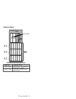

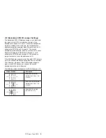


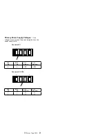
J12 Backplane SCSI ID Jumper Settings:
The Backplane SCSI ID Address Jumper, a pin block with
four pairs of pins (J12), is located on the rear of the
backplanes in banks C, D, and E. When two backplanes
are daisy-chained in the enclosure, the first backplane
address jumper (for example, Bank C) must be set to LO,
defining the SCSI IDs as 0 through 5. The second
backplane (in this example, bank D), must be set to either
Reverse, defining the SCSI IDs as 5 through 0, or HI,
defining the SCSI IDs as 8 through D. The default, no
jumper installed, is to set the addresses to LO.
If the SCSI adapter supports more than eight SCSI devices
per SCSI channel, the second backplane can be set either
HI or Reverse. However, if the SCSI adapter supports
eight or less SCSI devices per channel, the second
backplane must be set to Reverse.
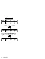
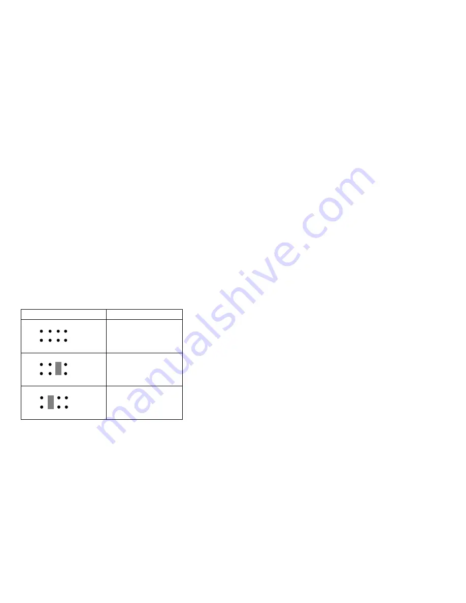
The following jumper settings are for SCSI ID jumper J12.
Jumper Position
Description
LO
J12
5 7
4 6
2
8
3
1
Sets SCSI IDs to low,
starting from 0 (bay 1) to
5 (bay 6)
LO
J12
5 7
4 6
2
8
3
1
Sets SCSI IDs to reverse,
starting from 5 (bay 1) to
0 (bay 6)
HI
J12
5 7
4 6
2
8
3
1
Sets SCSI IDs to high
(SCSI IDs 8 to D)
PC Server Type 3518
9


