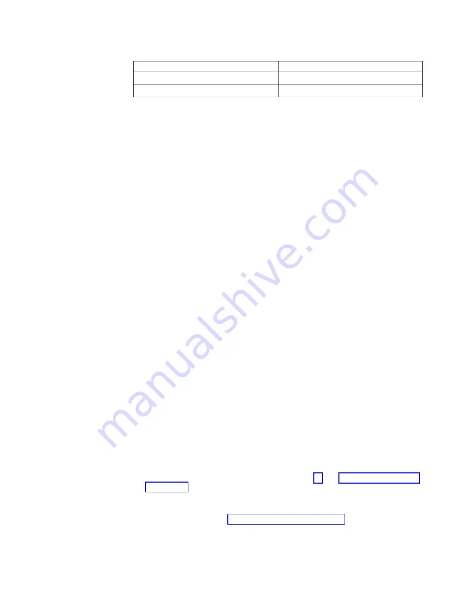
Table 7. IDs of simple-swap drives (continued)
Drive bay
ID
5
2
6
3
v
The simple-swap SATA hard disk drives connect to the SATA 0 through SATA 3
connectors on the system board as follows:
– System board end cable connector 0 connects to the SATA 0 connector on
the system board.
– System board end cable connector 1 connects to the SATA 1 connector on
the system board.
– System board end cable connector 2 connects to the SATA 2 connector on
the system board.
– System board end cable connector 3 connects to the SATA 3 connector on
the system board.
v
– Hard disk drive 0 connects to the SATA 0 connector on the system board.
– Hard disk drive 1 connects to the SATA
2
connector on the system board.
– Hard disk drive 2 connects to the SATA
1
connector on the system board.
– Hard disk drive 3 connects to the SATA 3 connector on the system board.
Note:
Under RAID mode:
1. In uEFI setup menu:
v
Drive 0 indicates hard disk drive 0.
v
Drive 1 indicates hard disk drive
2
.
v
Drive 2 indicates hard disk drive
1
.
v
Drive 3 indicates hard disk drive 3.
2. In MegaRAID Storage Manager utility:
v
Slot 0 indicates hard disk drive 0.
v
Slot 1 indicates hard disk drive
2
.
v
Slot 2 indicates hard disk drive
1
.
v
Slot 3 indicates hard disk drive 3.
Attention:
Simple-swap hard disk drives are not hot-swappable. Disconnect all
power from the server before you remove or install a simple-swap hard disk drive.
Note:
If you installed a ServeRAID adapter in the server, connect the other end of
the SATA signal cable to the connector on the ServeRAID adapter.
To install a simple-swap SATA hard disk drive, complete the following steps:
1. Read the safety information that begins on page vii and “Installation guidelines”
2. Turn off the server and peripheral devices and disconnect all external cables
and power cords.
3. Remove the bezel (see “Removing the bezel” on page 25).
4. Touch the static-protective package that contains the drive to any unpainted
metal surface on the server; then, remove the drive from the package and place
it on a static-protective surface.
Chapter 2. Installing optional devices
39
Summary of Contents for 2582
Page 1: ...System x3100 M4 Type 2582 Installation and User s Guide ...
Page 2: ......
Page 3: ...System x3100 M4 Type 2582 Installation and User s Guide ...
Page 8: ...vi System x3100 M4 Type 2582 Installation and User s Guide ...
Page 18: ...xvi System x3100 M4 Type 2582 Installation and User s Guide ...
Page 90: ...72 System x3100 M4 Type 2582 Installation and User s Guide ...
Page 100: ...82 System x3100 M4 Type 2582 Installation and User s Guide ...
Page 106: ...88 System x3100 M4 Type 2582 Installation and User s Guide ...
Page 107: ......
Page 108: ... Part Number 00D3167 Printed in USA 1P P N 00D3167 ...


