background image

 Chapter 3: Basic Operations        

27

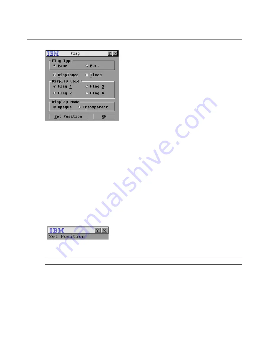
Figure 3.8:  Flag Window

Determining the display of the status flag

1.

Select 

Name 

or 

Port


to determine what information will be displayed.

2.

Select 

Displayed 

to show the flag all the time or select 

Timed

 to display the flag for only five 

seconds after switching.

3.

Select a flag color in the 

Display Color 

area.

4.

In the 

Display Mode 

area, select 

Opaque 

for a solid color flag or select 

Transparent 

to see 

the desktop through the flag.

5.

To position the status flag on the desktop:

a.

Click 

Set Position

 to gain access to the Set Position window.

b.

Left-click on the title bar and drag to the location that you want.

c.

Right-click to return to the Flag window.

Figure 3.9:  Set Position Window

NOTE:

 Changes made to the flag position are not saved until you click 

OK

 in the Flag window.

6.

Click 

OK

 to save the settings.

-or-
Click 

X

 to exit without saving changes.

Summary of Contents for 09N4290

Page 1: ......

Page 2: ......

Page 3: ...Console Switch Installation and User s Guide...

Page 4: ......

Page 5: ......

Page 6: ...uations that can be potentially lethal or extremely haz ardous to you A danger statement is placed just before the description of a potentially lethal or extremely hazardous procedure step or situatio...

Page 7: ......

Page 8: ......

Page 9: ...nstalling the Console Switch 11 Tiering Multiple Console Switches 13 Adding Earlier model Switches 14 Configuring the Console Switch System 16 Chapter 3 Basic Operations 17 Controlling the System at t...

Page 10: ...adcasting to Servers 34 Changing the Switch Mode 36 Setting the Keyboard Country Code 37 Appendices 39 Appendix A Firmware Upgrades 39 Appendix B Technical Specifications 41 Appendix C Notices 42 Appe...

Page 11: ...nfigured Main Window 18 Figure 3 2 Setup Window 22 Figure 3 3 Names Window 22 Figure 3 4 Name Modify Window 23 Figure 3 5 Devices Window 24 Figure 3 6 Device Modify Window 24 Figure 3 7 Menu Window 25...

Page 12: ...xii List of Figures...

Page 13: ...Refresh Rate 2 Table 2 1 Earlier model Switches 14 Table 3 1 OSCAR Interface Status Symbols 18 Table 3 2 OSCAR Interface Navigation Basics 20 Table 3 3 Setup Features to Manage Routine Tasks for the S...

Page 14: ...xiv List of Tables...

Page 15: ...he switch cable is powered directly from the server and provides Keep Alive functionality even if the console switch is not turned on Keep Alive functionality enables the server to operate properly wi...

Page 16: ...t number enabling you to assign a unique server name Security The OSCAR interface enables you to protect the system with a screen saver password After a user defined time the screen saver mode engages...

Page 17: ...nsion The 1x8 console switch supports up to 8 directly attached servers and the 2x16 console switch supports up to16 directly attached servers Each model can conveniently scale to support additional s...

Page 18: ...recautions Use the following safety guidelines to help ensure your own personal safety and to help protect the system and working environment from potential damage Console Switch tiered Earlier model...

Page 19: ...Chapter 1 Product Overview 5...

Page 20: ...len into the product The console switch has been exposed to water The console switch has been dropped or damaged The console switch does not operate correctly when you follow the operating instruction...

Page 21: ...s Consult a licensed electrician or the power company for site modifications Always follow the local and national wiring rules Rack Mounting of Systems Refer to the rack installation documentation acc...

Page 22: ...8 IBM Console Switch Installation and User s Guide...

Page 23: ...d server One IBM 3M Console Switch Cable PS 2 per attached switch One Phillips screwdriver Rack Mounting the Console Switch Before installing the console switch and other components in the rack if not...

Page 24: ...installation Horizontal installation in the 1 U rack mounting space NOTE The filler panel must be placed in front of the rack when the console switch is mounted in the horizontal 1 U orientation 1 Re...

Page 25: ...he Console Switch Connect the supplied power cord into the back of the console switch and then into an appropriate power source Figure 2 3 illustrates one possible configuration for the console switch...

Page 26: ...will be connecting to the console switch 3 Connect the RJ 45 connector on the PS 2 or USB switch cable to an Analog Rack Interface ARI port on the back of the console switch 4 Repeat steps 2 to 4 for...

Page 27: ...servers on the 2x16 console switch The example in Figure 2 4 shows one console switch tiered under the main switch enabling the connection of up to 15 primary servers and 16 secondary servers In this...

Page 28: ...The system will automatically tier the two switches together as one All servers connected to the tiered console switch will display on the main console switch server list in the OSCAR interface 5 Rep...

Page 29: ...PS 2 switch cable to an ARI port on the back of the console switch 4 Connect the servers to the tiered switch according to the instructions included with that device 5 Power cycle the tiered switch t...

Page 30: ...or the 2x16 console switch repeat steps 1 and 2 for the local port set labeled B 4 Bundle and label the cables for easy identification Configuring the Console Switch System With the console switch sys...

Page 31: ...Servers Use the OSCAR Main window to view configure and control servers directly connected to the console switch View the servers by name or port You will see an OSCAR interface generated port list b...

Page 32: ...olumns of the Main window The following table describes the status symbols Table 3 1 OSCAR Interface Status Symbols Symbol Description The switch cable is online green circle The switch cable is offli...

Page 33: ...r NOTE The status flag displays on the desktop and shows the name or the port number of the selected server or the status of the selected port NOTE To clear all directly connected offline switch cable...

Page 34: ...ne In the Main window it closes the OSCAR interface and returns to the flag In a message window it closes the pop up window and returns to the current window Alt Hotkey Opens windows selects or checks...

Page 35: ...ottom of a list Delete Deletes characters in a field Table 3 2 OSCAR Interface Navigation Basics Continued Table 3 3 Setup Features to Manage Routine Tasks for the Servers Feature Purpose Menu Change...

Page 36: ...t order Names are stored in the switch cable so even if you move the cable or server to another ARI port the name and configuration will be recognized by the switch NOTE If a server is turned off its...

Page 37: ...ot saved until you click OK in the Names window 4 Repeat steps 1 to 3 for each server in the system 5 Click OK in the Names window to save the changes or Click X or press Esc to exit the window withou...

Page 38: ...he console switch discovers a tiered switch the port numbering changes to accommodate each server under that switch For example if the switch is connected to ARI port 6 the switch port would be listed...

Page 39: ...rder alters how servers will display in several screens including the Main Devices and Broadcast windows Accessing the Menu window 1 Press Print Screen to launch the OSCAR interface The Main window op...

Page 40: ...of the selected port Use the Flag window to configure the flag to display by server name or port number or to change the flag color opacity display time and location on the desktop Accessing the Flag...

Page 41: ...4 In the Display Mode area select Opaque for a solid color flag or select Transparent to see the desktop through the flag 5 To position the status flag on the desktop a Click Set Position to gain acce...

Page 42: ...et you will have to enter the password before you can access the Security window Accessing the Security window 1 Press Print Screen to launch the OSCAR interface The Main window opens 2 Click Setup Se...

Page 43: ...password protection from the console 1 From the Main window click Setup Security the Password window opens Type the password then click OK 2 In the Security window click in the New field and press En...

Page 44: ...screen saver 1 In the Security window clear the Enable Screen Saver check box 2 Click OK Turning on the screen saver After the screen saver is enabled press Print Screen then press Pause Displaying Ve...

Page 45: ...purposes only 5 Click X to close the Cable Version window Figure 3 13 Cable Version Window NOTE You can use the Reset button to reset the PS 2 switch cable This activity is only relevant when the con...

Page 46: ...these peripheral devices by issuing a reset command 1 Press Print Screen The Main window opens 2 Click Commands Device Reset A message window opens requesting that you confirm the reset 3 Click OK A m...

Page 47: ...3 to 255 of time before the scan moves to the next server in the sequence 5 Click OK Removing a server from the scan list 1 In the Scan window clear the check box next to the server to be removed or D...

Page 48: ...ce is not open Scanning will stop at the currently selected server or Press Print Screen The Main window opens 2 Click Commands The Commands window opens 3 Clear the Scan Enable check box Broadcasting...

Page 49: ...the mouse must be in exactly the same place on all screens Because these conditions are extremely difficult to achieve broadcasting mouse movements to multiple systems can have unpredictable results B...

Page 50: ...dcast Enable check box Changing the Switch Mode The console switch enables you to connect to attached servers using two methods Preemptive and Cooperative Select Preemptive default setting to enable t...

Page 51: ...period in seconds 5 Click OK to save the Switch Mode and Share Mode settings Setting the Keyboard Country Code The console switch enables you to set the keyboard country code servers for the Sun serve...

Page 52: ...and User s Guide 3 Select the keyboard country code for the Sun servers Click OK The Keyboard Warning window opens Figure 3 20 Keyboard Warning Window 4 Click OK on the Keyboard Warning window to save...

Page 53: ...switch Make a note of which COM port you have chosen then turn on the switch 2 Go to http www ibm com pc support and click on Downloads and drivers Search on the product name to access the firmware up...

Page 54: ...ced Port settings verify that the FIFO buffers are selected and that the receive buffer is set to High ATTENTION While upgrading do not use the server for anything else or switch between windows Close...

Page 55: ...ns Dimensions H x W x D 4 45 cm x 43 18 cm x 27 94 cm 1 U form factor 1 75 in x 17 00 in x 11 00 in Weight 3 6 kg 8 lb without cables Heat Dissipation 92 Btu Hr Airflow 8 CFM Power Consumption 12 5 Wa...

Page 56: ...ES THIS PUBLICATION AS IS WITHOUT WARRANTY OF ANY KIND EITHER EXPRESS OR IMPLIED INCLUDING BUT NOT LIMITED TO THE IMPLIED WARRANTIES OF NON INFRINGEMENT MERCHANTABILITY OR FITNESS FOR A PARTICULAR PUR...

Page 57: ...n if available and may not include user manuals or all program functionality Product recycling and disposal This unit contains materials such as circuit boards cables electromagnetic compatibility gas...

Page 58: ...sed by using other than recommended cables and connectors or by unauthorized changes or modifications to this equipment Unauthorized changes or modifications could void the user s authority to operate...

Page 59: ...ards This product has been tested and found to comply with the limits for Class A Information Technology Equipment according to CISPR 22 European Standard EN 55022 The limits for Class A equipment wer...

Page 60: ...46 IBM Console Switch Installation and User s Guide...

Page 61: ...11 installing 11 rack mounting 9 supplied with 9 technical specifications 41 tiered switch configuration 13 tiering 10 upgrading 39 viewing status 18 console switch PS 2 1 console switch USB 2 consol...

Page 62: ...resetting keyboard and mouse 32 S scan list removing a server 33 screen saver mode 29 security 2 server adding to scan list 32 configuring for soft switching 19 disconnecting users 19 removing from s...

Page 63: ......

Page 64: ...31R3148 590 479 999A...

Reviews: