ibidi Heating System 4 Slides – Silver Line
Optional: To setup communication with the IncuControl Software, the USB cable must be connected
to the Temperature Controller and the computer (Section
To adjust the sample temperature, use the temperature sensor in the Temperature Adjustment Set
and plug it into the corresponding connector at the back of the Temperature Controller. The actual
temperature is shown in the lower left corner of the display (Figure
). The sensor is then placed
into the sample (Section
5.2
Start Operation of the ibidi Heating System 4 Slides
The ibidi Temperature Controller – Silver Line is switched on by the dip switch at the back. Make
sure the display shows “RUN” (see Section
). The system immediately starts heating up the
heated devices (Heated Plate, Heated Lid).
WARNING
– Be aware that when the system is switched on, 10V DC voltage is
applied to the underside of the glass plate. Do not touch the underside or contact it with
anything conductive! This could cause a short circuit that may destroy the controller
and/or the lid.
If you are not sure which temperature is set (e.g., when operating the system the first time), it is
recommended to check the settings without your sample.
5.3
Setting Parameters in the Front Display
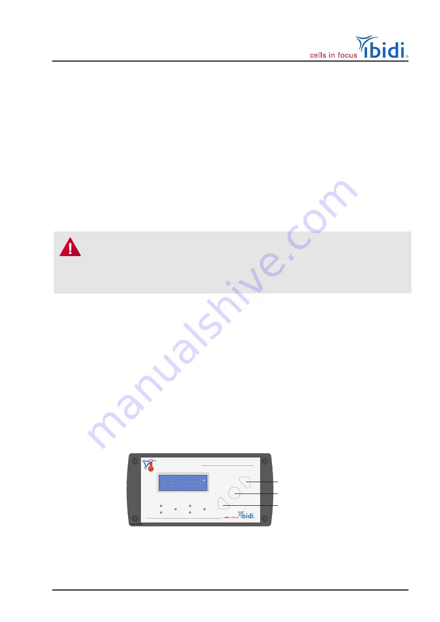
All control parameters can be manually set on the controller using the buttons and the display of the
front panel.
The cursor position is indicated with square brackets (“
[
]
”). You can move the cursor using the
“left” and “right” buttons. If you want to select a parameter or a function, press the round button
and the square brackets will change to angle brackets (“
<
>
”). Now you can change the value with
the “up” and “down” buttons. To confirm the changed value, press the round button once more.
1
3
4
6
2
5
ibidi Temperature Controller
Plate
I 38.0
S[ 38.0]
Run
Lid
42.1
42.0
Setup
N.C.
1
Up/right
Down/left
Round button
Figure 12: ibidi Temperature Controller – Silver Line front display and set buttons.
Instruction Manual
23
Version 1.0 (August 1, 2022)


