INSTALLATION AND OPERATION INSTRUCTIONS
3-6
SL 35-199, SL 45-260 MODULATING GAS BOILERS
NOTE
The safety warning regarding
burner refractory on page
4-2 of this manual must be
observed.
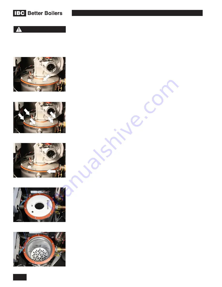
3.4.1 Gaining access to combustion chamber, burner
removal instructions
1.
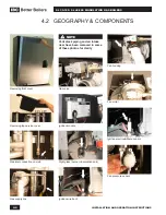
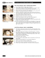
Remove fan and gas valve assembly.
See “Fan and gas valve removal
instructions” on page 4-6 of this manual.
2.
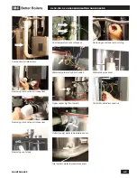
Disconnect the igniter cable, gas valve cable and 2 fan plugs and move them
out of the way.
3.
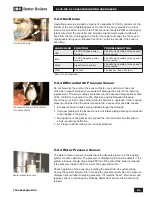
Remove the two screws that secure the igniter to the lid using a # 2 Phillips
screwdriver.
4.
Carefully remove the igniter by sliding it straight up.
5.
Remove the igniter gasket and place parts on a clean dry area.
6.
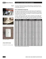
Remove the 6 hex nuts that attach the heat exchanger lid to the heat
exchanger. A 10 mm open end wrench or socket will be required.
7.
With a permanent marker or equivalent, make an alignment mark between
the lid, gasket and heat exchanger.
8.
Before removing the lid, it is important to be positioned directly above it to ensure
a straight up extraction. Failing to do this may result in refractory damage.
9.
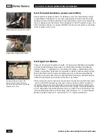
Slowly lift the lid-burner assembly off the heat exchanger. The refractory
should remain in place in the combustion chamber shoulder. Note that
there is less than 1/8” (3 mm) clearance between the burner walls and the
refractory. Care must be observed to ensure minimal contact between these
parts to prevent refractory cracking.
10.
Place the lid with the burner attached, on a clean dry area.
11.
With a permanent marker or equivalent, make an alignment mark on the
refractory lining it up with the same mark made earlier between the lid and
heat exchanger.
12.
Carefully remove the refractory and place in a clean dry area.
13.
If burner needs to be removed, gradually loosen up the 3 screws that secure
the burner to the heat exchanger lid using a #2 Phillips screwdriver. Remove
screws and burner.
RE-ASSEMBLY
1.
Inspect burner gasket. Look for cracks, deterioration or signs of gas bypass.
Replace if necessary.
2.
Place heat exchanger lid on a flat surface and position the gasket on the lid,
aligning it with the screw holes.
3.
Install the burner in place with its 4 screws, tightening the screws gradually and
in a cross sequence. Do not over tighten, hand tight plus 1/8 turn should be
sufficient to maintain a good seal and prevent deformation of the burner flange.
4.
Inspect refractory for cracks, degradation and flatness. If in doubt, replace
with a new one.
5.
If installing a new refractory, first place it onto the lid, aligning it at the igniter
hole, then make an alignment mark on the refractory to coincide with the
previously made line on the lid.
6.
Carefully insert refractory into heat exchanger combustion chamber, using
the alignment marks for proper positioning.
7.
Ensure that the lid (orange) gasket is in good condition and is in place and flat.
8.
Carefully insert the lid-burner assembly straight down ensuring limited contact
between burner and refractory and observing the alignment markings.
9.
Install the 6 hex nuts to secure the lid in place, tighten by hand, then an extra
1/2 to 1 turn. Caution! Over-tightening these nuts will cause lid to warp and
possibly leak fumes or flames.
10.
Re-install igniter, tightening its screws by hand, then an extra 1/8 turn.
11.
Re-attach igniter wire to igniter, gas vlave cable and the 2 fan plugs.
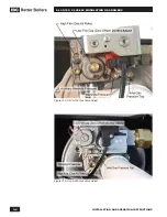
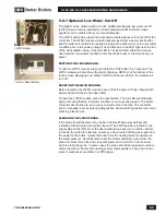
Heat Exchanger Gasket
Combustion Chamber Refractory
Heat Exchanger Lid
Heat Exchanger Lid Hex Nuts
Heat Exchanger revealed
Summary of Contents for SL 35-199
Page 71: ...SERVICE RECORD DATE LICENSED CONTRACTOR DESCRIPTION OF WORK DONE...
Page 72: ...NOTES...
Page 73: ...NOTES...

