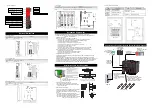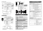
4. EtherCAT (REC-GW-EC)
Refer to the instruction manuals for each field network master unit for the details.
Connector Name
EtherCAT Connector
Remarks
Cable Side
Ethernet ANSI/TIA/EIA-568-B Category 5
and above 8P8C modular plug equipped
with shield (RJ45)
Please prepare
separately
Controller Side
Ethernet ANSI/TIA/EIA-568-B Category 5
and above 8P8C modular Jack equipped
with shield (RJ45)
Pin
No.
Signal Name
Description
Applicable cable
diameter
1 TD+
Data
It is recommended
to prepare a
straight STP cable
in Category 5 or
above for the
Ethernet cable.
2 TD-
Data sending-
3 RD+
Data re
4 -
Disconnected
5 -
Disconnected
6 RD-
Data receiving-
7 -
Disconnected
8 -
Disconnected
5. EtherNet/IP (REC-GW-EP)
7. PROFINET IO (REC-GW-PRT)
Refer to the instruction manuals for each field network master unit for the details.
Connector Name
EtherNet/IP, PROFINET IO Connector
Remarks
Cable Side
Ethernet ANSI/TIA/EIA-568-B Category 5
and above 8P8C modular plug equipped
with shield (RJ45)
Please prepare
separately
Controller Side
Ethernet ANSI/TIA/EIA-568-B Category 5
and above 8P8C modular Jack equipped
with shield (RJ45)
Pin
No.
Signal Name
Description
Applicable cable
diameter
1 TD+
Data
It is recommended
to prepare a
straight STP cable
in Category 5 or
above for the
Ethernet cable.
2 TD-
Data sending-
3 RD+
Data re
4 -
Disconnected
5 -
Disconnected
6 RD-
Data receiving-
7 -
Disconnected
8 -
Disconnected
6. PROFIBUS-DP (REC-GW-PR)
Refer to the instruction manuals for each field network master unit for the details.
Connector Name
PROFIBUS-DP Connector
Remarks
Cable Side
9-pin D-sub Connector (Male)
Please prepare separately
Controller Side
9-pin D-sub Connector (Female)
Pin
No.
Signal Name
Description
Applicable cable diameter
1 NC
Disconnected
Dedicated cable for
PROFIBUS-DP
(Type A: EN5017)
2 NC
Disconnected
3 B-Line
Communication Line B (RS485)
4 RTS
Request for Sending
5 GND
Signal GND (Insulation)
6 +5V
+5V Output (Insulation)
7 NC
Disconnected
8 A-Line
Communication Line A (RS485)
9 NC
Disconnected
Starting Procedures
When using this product for the first time, make sure to avoid mistakes and incorrect wiring by referring to
the procedure below.
In this section, explains how to start up especially for REC system. Follow an instruction manual (DVD) for
each device for how to link to other devices, controllers and actuators that are linked in the network.
Troubleshooting (LED Display)
On REC Gateway Unit, there are the monitor LEDs for the field network and communication.
You can confirm the communication establishment and also communication errors on these LEDs.
Refer to “Names for Each Part” for the position and name of each LED lamp.
1. LED Display on EC Gateway Unit
Panel
Display
Color
Status
Explanation
T RUN
GN
Illuminating
Inside bus communication in normal conditions
Flashing
Waiting for initializing communication
OR
Illuminating
Inside bus communication in error
SYS
GN
Illuminating
Operating in normal conditions
OR
Illuminating
Gateway alarm being generated
STOP
RD
Illuminating
Stop switch on teaching pendant valid (while pressed and held)
OFF
Stop switch on teaching pendant invalid
MODE
GN
Illuminating
In AUTO (automatic operation) Mode
OFF
In MANU (manual operation) Mode
C ERR
OR
Illuminating
Error occurred in field network
OFF
Field network operating in normal conditions
STATUS 0
-
-
Differs depending on field network (Refer to Field Network
Communication Conditions from 1 to 7)
STATUS 1
-
-
Differs depending on field network (Refer to Field Network
Communication Conditions from 1 to 7)
2. LED Display on EC Connection Unit
Panel
Display
Color
Status
Explanation
T RUN
GN
Illuminating
Inside bus communication in normal conditions
Flashing
Waiting for initializing communication, Initializing
communication failed
OR
Illuminating
Inside bus communication in error
SYS
GN
Illuminating
Servo ON
OFF
Servo OFF
RD
Illuminating
Alarm being generated, stop switch on teaching pendant
valid (while pressed and held)
Forward
End
GN
Illuminating
Movement to forward end completed
OFF
Stop
RD
Illuminating
Alarm being generated
Backward
End
GN
Illuminating
Movement to backward end completed
OFF
Stop
[Field Network Communication Conditions]
1. CC-Link (REC-GW-CC)
Name
Panel
Display
Color
Status
Explanation
STATUS 0
RUN
GN
Illuminating
Succeeded in refresh and polling reception
after getting into network, or succeeded in
refresh reception
OFF
1. Not in network
2. Carrier detected for channel
3. Timeover
4. In hardware reset
STATUS 1
ERR
OR
Illuminating
1. CRC Error
2. Station number setting error at reset release
(65 stations or more including 0 or occupied
station number)
3. Baud rate setting error at reset release
Flashing
(Flash for
0.4sec)
Numbers changed from station numbers and
baud rate setting numbers at reset release
OFF
1. Communication in normal conditions
2. In hardware reset
5 1
9 6
Cable
Shield
Red B line (Positive side)
Green A line (Negative side)
Master Unit
Slave Devices
REC EtherCAT Type
Ethernet Straight Cable Category 5 or more
Double shielded cable braided with aluminum foil recommended
(Note) Terminal resistance is not required
Top View of
Connector on
EC Gateway
Unit side
1
8
1
8
OUT
IN
Top View of
Connector on
EC Gateway
Unit side
1
8
5
9
6
1
Top View of
Connector on
EC Gateway
Unit side
Slave Devices
REC PROFIBUS-DP Type
Master Unit
Grounding resistance at 100
Ω
or less
(Class D grounding)
Master Unit
Switching Hub
Slave Devices
REC-
EtherNet/IP Type
or
REC-
PROFINET IO Type
Ethernet Straight Cable,
Category 5 or more
Double shielded cable braided with
aluminum foil recommended
No →
Check on Safety Circuit
Confirm that the stop circuit (drive source cutoff circuit) works in normal conditions.
↓Yes
No →
Check of Packed Items
Are all the delivered items present?
Contact your local IAI distributor
Installation and Wiring
* Refer to [Installation and Noise Elimination] in this first step guide
Install the controller and actuator and perform wiring according.
Important Check Item
•
Is frame ground (FG) connected?
•
Has the noise countermeasure been taken?
↓
← Yes
Initial Settings (Setup of ELECYLINDER) * Teaching Tool is required
Establish the parameter settings for each ELECYLINDER.
PLC (Master Unit) Baud Rate
* Refer to PLC Instruction Manual.
Have the settings established for the PLC node addresses (station
numbers) and the baud rate.
Initial Settings (Setup of Gateway) * Gateway parameter setting tool is required
Have the settings done for the axis number setting, mode settings, field network communication speed, node addresses
(station numbers) and so on to suit to the system.
↓
No →
Power Supply
1) Supply the power to PLC (master unit).
2) Supply the power to REC.
Check the status of LED lamps to see the
cause of the error to have an appropriate
counteraction. Do the whole process from
the start if the cause of the error is not
clear.
↓
Communication Establishment Check
•
Confirm that the communication has been established with the
LED lamp on EC Gateway Unit.
* Refer to “Troubleshooting” in this first step guide
•
Confirm that communication is established also on PLC (master unit).
* Refer to PLC Instruction Manual.
Check the circuit.
↓Yes
Now, it is succeeded to establish communication and ready for operation.
Move on to the system operation check and adjustment.
↓
Assembling REC (Linking up Units)
Join the units to use such as the EC Gateway Unit, EC Connection Unit and REC Terminal Unit.
↓
↓
Important Check Item
•
Is the control sequence applicable for
the continuous mode and the system?
↓Yes


