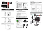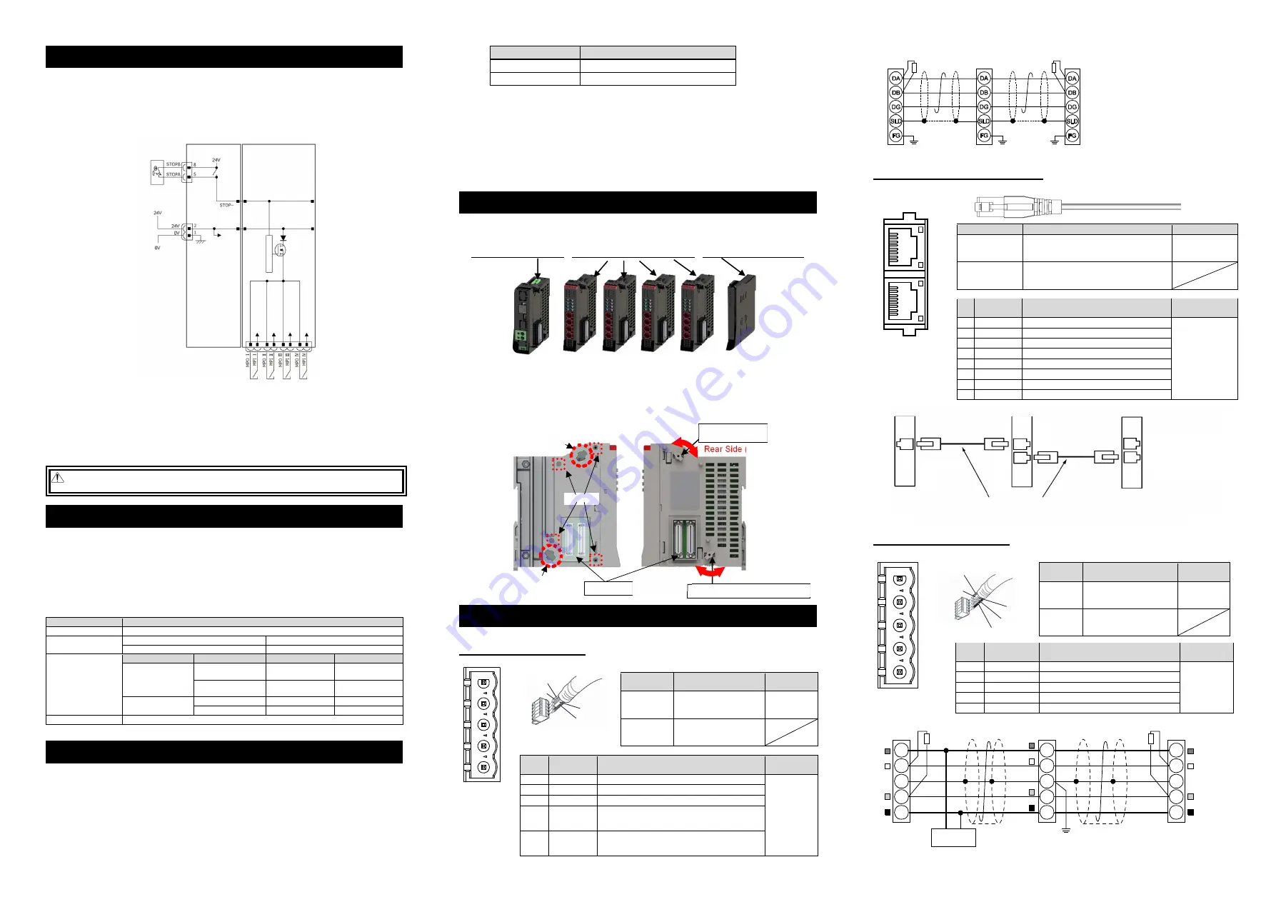
Master Unit
Slave Devices
REC CC-Link IE Field Type
Ethernet Straight Cable Category 5e or more
Double shielded cable braided with aluminum foil recommended
(Note) Terminal resistance is not required
There is no
distinction of IN/OUT
on the connector.
Rear Side (Link)
Link Upper Parts
Operation Part
[
C
]
[A]
Link Bottom Parts Operation Part
[B]
Connector
Panel Side (Unlink)
Panel Side
(Unlink)
Rear Side (Link)
Power Supply and Stop Circuit (Example)
In the diagram below shows a circuit related to REC system drive source cutoff. For REC system, 24V power is supplied
from the EC Gateway Unit, but the circuit related to the drive-source cutoff is on the EC Connection Unit side.
•
Each unit of EC Connection Unit possesses a drive cutoff circuit by semiconductor gathered for the four axes, and
the motor power source is to be cut off by the stop switch on the teaching pendant. Also, the drive source cutoff
circuit by semiconductor possesses features to detect the over current and to limit the in-rush current.
•
Each driver unit possesses an interface (Drive source cutoff connector: MPI/MPO) available for external drive
source cutoff prepared for each axis.
Note 1 If nothing is connected to the SIO connector, short-circuit should be made inside the controller.
Note
●
When externally shutting off the motor drive source, connect a contact such as a relay to the wiring between the
MPI* and MPO* terminals.
●
When supplying power by turning ON/OFF 24 VDC, leave 0 V connected and supply/cut off +24 V.
●
Make sure to have the right cable diameter and length that would not have the voltage dropped at the wiring of the
drive cutoff connector.
●
There may be a case of an alarm being generated because of the voltage drop at the controller power supply due to
inappropriate cable diameter or length. In such a case, adjust the output voltage of the power supply to keep 24V for
the supply to the controller.
Warning : Note that the stop switch on the teaching pendant cannot have a stop for the system side even though it
can have a stop for all the actuators connected to REC System.
Current Amperage
The current amperage should be divided into the control power capacity and motor power capacity.
Each power supply should be input from the 24V power supply connector on the EC Gateway Unit.
The necessary capacity of the current amperage should be figured out by [Total of control power capacity of
used units] + [Total of motor power capacity of used actuators].
It is necessary that the rated current of 24V power supply satisfies the rated current of the motor power
capacity and the peak current satisfies the maximum current of the motor power capacity. However, when
several axes get connected, unless all the actuators operates at the same time, the rated current and
maximum current would not flow at the same time, thus the calculation should not be simply the total of all
the axes.
The specifications related to the power capacities should be as shown below.
Note When ELECYLINDER * 4 axes are connected to EC Connection Unit
Restrictions in Unit Connection
(1) Number of EC Connection Units to Connect
The maximum number of control axes to be connected to one EC Gateway Unit should be 16 axes.
From the structural perspective of the unit, it can accept connection without any upper limit, but make it
accept 4 units (for 16 axes) of EC Connection Units at the maximum. (One unit occupies domains and
axis numbers for four axes regardless of whether to connect ELECYLINDER to the units or not.) Have
two EC Gateway Units or more in the construction when it is necessary to control 17 axes or more of actuators.
(2) Current Restrictions
Shown below is the restricting values of current for selecting calculation.
Item
Restricting Value of Current for Selecting Calculation
Control Power Supply (CP)
9.0A or less
Motor Power Supply (MP)
37.5A or less
Shown below is some examples for calculation.
[Control Power Supply] * EC Gateway Unit should be excluded from the target for calculation.
When ELECYLINDER × 16 axes: EC Connection Unit 0.1A × 4 = 0.4A
⇒
OK
[Motor Power Supply]
When ELECYLINDER (with power-saving setting inactivated) × 16 axes:
EC Connection Unit Rated Current 2.3A × 16 axes = 36.8A => OK
Note For the models with no description of the rated current for the motor current amperage, calculate with the
maximum current.
Note When the operation pattern is to have all the axes operate acceleration and deceleration only and the operation
duty is 100%, it is necessary that the calculation is done with the maximum current for the motor power supply.
REC system is capable to link 4 units (for 16 axes) at the maximum with the EC Gateway Unit allocated at
the left end as the interface for the field network connection and freely construct with combination of
multiple EC Connection Units. There is an order of allocation for each unit.
EC Gateway Unit (Left End)
-
EC Connection Unit
(
No Order among
)-
REC Terminal Unit (Right End)
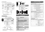
Each unit should be linked in the process shown below. (Make sure it gets linked before connected to the DIN rails.)
1) Twist the operation parts of the link upper parts and the link bottom parts towards the panel side and
place them at the panel side end.
2) Adjust the position of two units so the link upper parts come to Point [A], link bottom parts to [B] and the
four positioning bosses to [C] and all the six points fit to each other.
3) Once positioning is done, firmly insert the connectors at two points.
4) Twist the operation parts of the link upper parts and the link bottom parts towards the rear side till they
make click feeling.
Field Network Wirings and Settings
The field network connector is allocated on the top of the EC Gateway Unit. Refer to “Names for Each Part”.
1. CC-Link (REC-GW-CC)
Refer to the instruction manuals for each field network master unit for the details.
Connector
Name
CC-Link Connector
Remarks
Cable Side
MSTB2.5/5-STF-5.08 AU
(Manufactured by
PHOENIX CONTACT)
Enclosed in
standard
package
Controller Side
MSTB2.5/5-GF-5.08 AU
(Manufactured by
PHOENIX CONTACT)
Pin No.
Signal Name
(Color)
Description
Applicable
cable diameter
1
DA (BL)
Communication Line A
Dedicated
cable for CC-
Link
2
DB (WT)
Communication Line B
3
DG (YW)
Digital Ground
4
SLD
Connect the shield of the shielded cable
(Connected inside to 5-pin FG and control power supply
connector 1-pin FG)
5
FG
Frame Ground
(Connected inside to 4-pin SLD and control power supply
connector 1-pin FG)
2. CC-Link IE Field (REC-GW-CIE)
Refer to the instruction manuals for each field network master unit for the details.
Connector Name
CC-Link IE Field Connector
Remarks
Cable Side
Ethernet ANSI/TIA/EIA-568-B Category 5e
and above 8P8C modular plug equipped
with shield (RJ45)
Please prepare
separately
Controller Side
Ethernet ANSI/TIA/EIA-568-B Category 5e
and above 8P8C modular Jack equipped
with shield (RJ45)
Pin
No.
Signal Name
Description
Applicable cable
diameter
1 TP0+
Data 0+
It is recommended
to prepare a
straight STP cable
in Category 5e or
above for the
Ethernet cable.
2 TP0-
Data 0-
3 TP1+
Data 1+
4 TP2+
Data 2+
5 TP2-
Data 2-
6 TP1-
Data 1-
7 TP3+
Data 3+
8 TP3-
Data 3-
3. DeviceNet (REC-GW-DV)
Refer to the instruction manuals for each field network master unit for the details.
Connector
Name
DeviceNet Connector
Remarks
Cable Side
MSTB2.5/5-STF-5.08 AU M
(Manufactured
by PHOENIX CONTACT)
Enclosed in
standard
package
Controller
Side
MSTB2.5/5-GF-5.08 AU
(Manufactured
by PHOENIX CONTACT)
Pin No.
Signal Name
(Color)
Description
Applicable
cable diameter
1
V- (BK)
Power Supply Cable Negative Side
Dedicated
cable for
DeviceNet
2
CAN L (BL)
Communication Data Low Side
3
-
Shield
4
CAN H (WT)
Communication Data High Side
5
V+ (RD)
Power Supply Cable Positive Side
Item
Specification
Power Supply Voltage
24V DC ±10%
Control Power Capacity
(for one unit)
EC Gateway Unit
0.8A
EC Connection Unit
0.1A
Motor power capacity
(1 axis per actuator)
Motor type
Rated Current
Max. current
35P/42P/56P
When power-saving
setting inactivated
2.3A
3.9A
When power-saving
setting activated
-
2.2A
28P
S3□/RR3□Type
-
2.2A
Slim and Small Type
-
2.0A
In-Rush Current (Note)
40A
(with in-rush current limiting circuit)
Linking Units
Top View of
Connector on
EC Gateway
Unit side
L.ER
LINK
L.ER
LINK
Shield
BL (CAN L)
RD (V+)
WT (CAN H)
BK (V-)
WT (DB)
BL (DA)
Shield (SLD)
YW (DG)
REC Gateway Unit
Control
Power
Stop Switch on
Teaching Pendant
EC
M
ot
or
P
owe
r S
uppl
y
Ⅰ
EC
M
ot
or
P
ow
er
S
up
ply
Ⅱ
EC
M
ot
or
P
ow
er
S
up
ply
Ⅲ
EC
M
ot
or
P
owe
r S
uppl
y
Ⅳ
High-
Sid
e P
rot
ec
tio
n C
irc
uit
Drive Source
Cutoff
Connector
RCON-EC Unit
Note 1
SIO Connector
24V Input
Connector
Slave Devices
REC-
CC-Link
Type
SLD and FG are internally connected.
Terminal Resistance is required
to be mounted on the terminal.
The terminal resistor differs depending on the type
of the dedicated cable for CC-Link.
• Cable FANC-SBH···130
Ω
1/2W
(High Performance Cable
dedicated for CC-Link)
• Cable FANC-SB······110
Ω
1/2W
(CC-Link Dedicated Cable)
Master Unit
Terminal
Resistance
Terminal
Resistance
Grounding resistance at 100
Ω
or less
(Class D grounding)
5
4
3
2
1
Top View of
Connector on
EC Gateway
Unit side
5
4
3
2
1
Top View of
Connector on
EC Gateway
Unit side
Slave Devices
REC-DeviceNet Type
V+
Drain
(Shield)
CAN_H
CAN_L
V-
RD
WT
BL
BK
RD
WT
BL
BK
V+
Drain
(Shield)
CAN_H
CAN_L
Grounding resistance at 100
Ω
or less
(Class D grounding)
V+
Drain
(Shield)
CAN_H
CAN_L
V-
RD
WT
BL
BK
Communication power needs to be
supplied by an external device.
Terminal Resistance is required
to be mounted on the terminal.
V-
Terminal Resistance
121
Ω
Master Unit
Terminal Resistance
121
Ω
24V
Power Supply


