


58
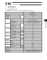
7. Specifi
cations
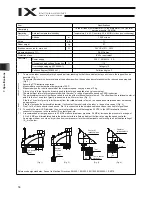
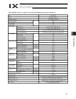
Item
Specifications
User piping
Three air tubes (outer diameter: 4, inner diameter: 2.5) (normal
service pressure: 0.8 MPa)
Ambient temperature/humidity
Temperature: 0 to 40 C, humidity: 20 to 85%RH or less (non-condensing)
Operating
environment
Altitude
m
1,000 or less
B
d
e
s
i
o
N
71
Air purge pressure (*11)
0.6 MPa max.
Protection class
IP65 or equivalent
Power supply
230 V
50/60 Hz
5 A
Allowable supply voltage fluctuation
%
10
Overvoltage category (IEC60664-1)
Category III
Controller
Pollution degree (IEC60664-1)
Pollution degree 3
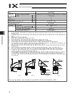
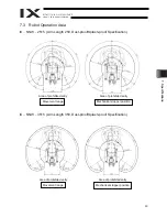
*1
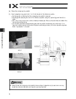
To move the robot horizontally at high speed, perform teaching so that the vertical axis stays as close to the top position as
possible. (Fig. 1)
To operate the robot with its vertical axis at the bottom position, the speed and acceleration must be reduced as appropriate.
(Fig. 2)
*2
Assuming PTP instruction operation.
*3
Measured at a constant ambient temperature of 20 C.
*4
Measured when the robot is operated at the maximum speed, carrying a load of 2 kg.
*5
A force of up to three times the dynamic push-in thrust may be applied at any given moment.
*6
The static thrust refers to thrust generated within the robot’ s range of operation based on PAPR instruction.
*7
The permissible moment of inertia converted to a value at the rotational center of axis 4. The offset from the rotational center of
axis 4 to the tool’ s center of gravity is assumed to be 40 mm or less. (Fig. 3)
If the tool’ s center of gravity is further away from the rota
tional center of axis 4, the speed and acceleration must be reduced
as appropriate.
*8
If the tool exceeds the permissible diameter, it will contact the robot inside the robot’ s range of movement. (Fig. 4)
*9
Pins 1 to 15 of the connector can be used. Pin 16 is connected to the shielded cable and cannot be used for signal lines.
*10
To enable the alarm LED indicator, the user must provide a circuit that supplies 24 VDC to the LED terminal in the user
connector in response to the controller I/O output signal, etc.
*11
A recommended air purge pressure is 0.3 MPa or above (maximum pressure: 0.6 MPa). Increase the pressure to a range of
0.3 to 0.6 MPa until immediately before the bellows starts to inflate, and adjust the flow rate using the speed controller.
As a purge medium, use clean, dry air free from compressor oil or other contaminants, conforming to an air filtration rating of
10 m or below.
Reference design standards: Annex I to Machine Directives, EN292-1, EN292-2, EN1050, EN60204-1, EN775
Top position
Tool
Tool
Tool
Tool
Bottom
position
Center of
rotational axis
Center of
rotational axis
Tool’ s center
of gravity
(Fig. 1)
(Fig. 2)
(Fig. 3)
(Fig. 4)
40
80
Brake power source for main unit
Robot weight
W
kg
24V DC ±10%
20W
21
Summary of Contents for Intelligent Actuator IX Series
Page 2: ......
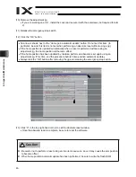
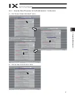
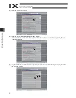
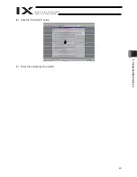
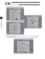
Page 55: ...49 6 Inspection Maintenance 6 Click the Servo OFF button 7 Press the emergency stop switch ...
Page 75: ......


