


61
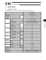
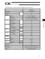
7. Specifi
cations
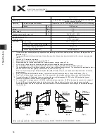
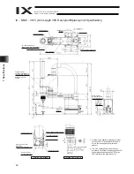
7.2 External
Dimensions
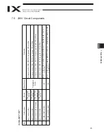
IX
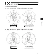
NNW
2515 (Arm Length 250, Dust-proof/Splash-proof Specification)
Arm 1 stopper
4 -
I
9
I
16, counterbore depth 0.5
4 (M
echanical end)
Spacer for user part
installation
Height 10, M4, depth 5 (*1)
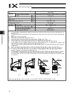
*1: External force applied to the spacers must
not exceed 30 N in the axial direction or 2
N
m in the rotating direction (for each
spacer).
*2: The LED operates only when the user
provides a circuit that receives controller I/O
output signal and supplies 24 VDC to the
LED terminal in the user connector.
Reference
surface
Reference
surface
ALM (indicator)
Arm 2 stopper
I
4 quick air-tube joint
(black, red, white; 3 locations)
BK SW (Brake-release switch)
Tapped hole for
peripheral installation (4
locations, M4, depth 12)
T-slot for
peripheral
installation
(M3, M4)
I
4 (red) quick joint
I
4 (black) quick joint
I
4 (white) quick joint
Detailed view of panel
(inner diameter)
User connector
Same on opposite
surface
Detailed view of arm tip
Purge air inlet:
Outer diameter
I
6
(inner diameter
I
4)
BK SW (Brake-release switch)
User connector
(15-pin connector)
ALM (red LED) (*2)
Summary of Contents for Intelligent Actuator IX Series
Page 2: ......
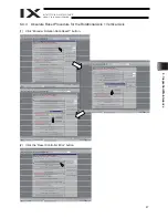
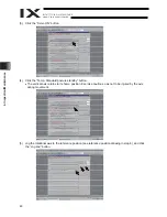
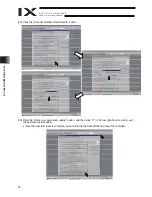
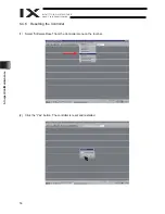
Page 55: ...49 6 Inspection Maintenance 6 Click the Servo OFF button 7 Press the emergency stop switch ...
Page 75: ......


