background image


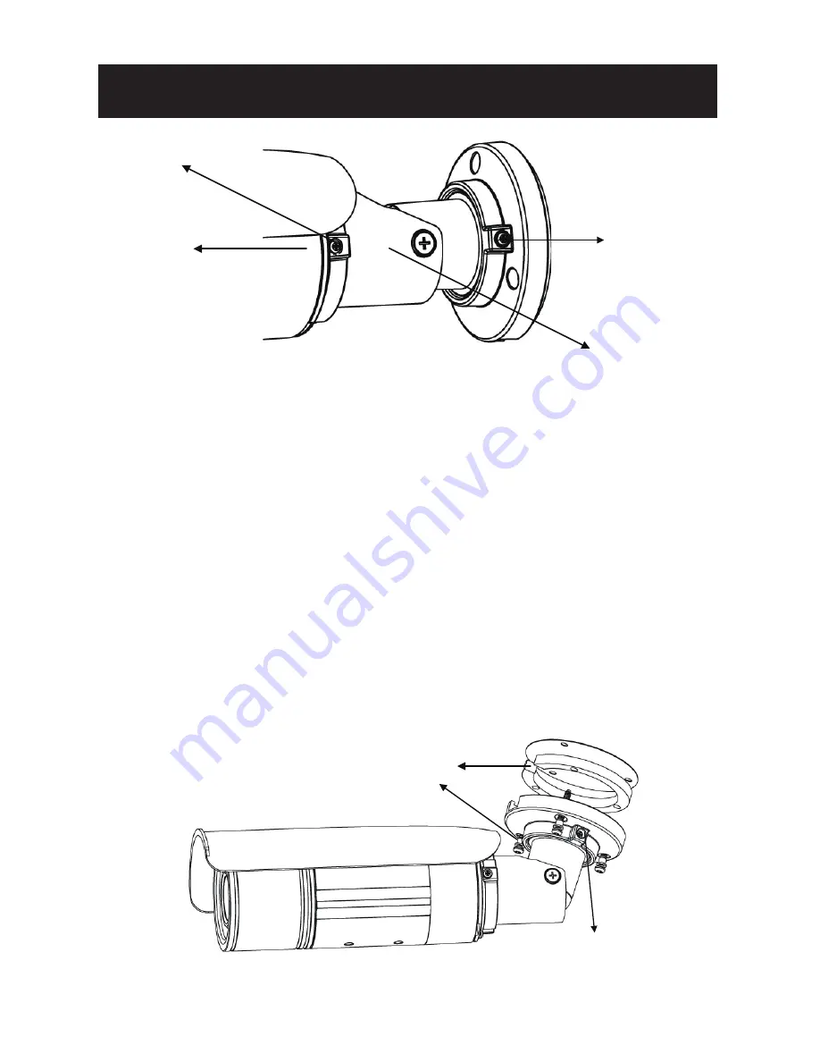
insulation cap 


pipe segment 


screws (

b.

)


mounting 

bracket


screw 

(

a.

)


INSTALLATION

10


3.1.3 Attaching the Camera to a Surface


1. Place the “rubber pad” inside the mounting bracket. 

2. Place the 3 “insulation caps” onto the “self tapping screws”.

3. Position the mounting bracket to the desired mounting 

location.

4. Screw the camera into the holes.

- For cement surfaces, insert the “plastic anchors” into the 

holes. Align the holes in the mounting bracket. Then use 

the “self tapping screws” to screw the camera into the 

holes.

- For any other surfaces, align the holes in the mounting 

bracket. Then use the “self tapping screws” to screw the 

camera into the holes. 

The mounting bracket can be loosened for easier cable 

installation. Loosen the screw (c.) on both sides to rotate the 

mounting bracket and adjust the cable. 


screw (

c.

)


rubber pad 

Summary of Contents for Ax41B1MVR

Page 1: ...mera Instruction Manual Before attempting to connect or operate this product please read these instructions carefully and save this manual for future use CONTENTS SAFETY INFORMATION Product Overview SPECIFICATION INSTALLATION 1 3 6 8 ...

Page 2: ...o mechanical vibrations close to fluorescent lamps or objects reflecting light under unstable light sources may cause flickering temperatures below 10 Celsius or 14 Fahrenheit and above 50 Celsius or 122 Fahrenheit for AX41B1MVR 5 Cleaning For maximum optical clarity the camera dome or lens must remain clean Use a soft dry cloth to remove finger prints or dust from the dome cover Use a blower to r...

Page 3: ... Lightning strike During prolonged inactivity please unplug the power cable and the video cable to avoid damage from lightning strike and power surges 10 Servicing To avoid electrical shock and to preserve the product warranty DO NOT disassembles the camera Refer servicing to qualified personnel only 11 Warning High voltage circuitry contained within the unit Do not disassemble to avoid electric s...

Page 4: ...e camera to capture images at 0 lux ICR Day Night Switching The camera incorporates a mechanical ICR filter to capture perfect pictures at any light level The camera switches between day and night modes automatically depending on the lighting conditions colour video image can capture at 0 3 lux and black white video at 0 lux ensuring crisp clear images at all times The camera s megapixel resolutio...

Page 5: ...ion 1 sunshield 2 pipe segment 3 mounting bracket 4 Power In Red Black 5 RJ 45 Ethernet Connector 6 BNC 9 Alarm Out Orange RS485 Green RS485 Yellow 10 GND Gray Alarm In Red Alarm Reset Brown 7 Audio Out Green 8 Audio In Red Future use Future use Future use Future use ...

Page 6: ...nnector DC12V AC24V 5 RJ 45 Ethernet Connector network connection Support PoE Power over Ethernet 6 BNC video output 7 Audio out Green audio output Future use 8 Audio in Red audio input Future use 9 Alarm out Orange alarm signal output port RS485 Green Future use RS485 Yellow Future use 10 GND ground electricity in electrical circuits Alarm in Red alarm signal input port Alarm Reset Brown for rese...

Page 7: ... to 1 3 75 sec Alarm Yes 1x Alarm in 1x Alarm out Day Night Mode Mechanical ICR Filter Minimum illumination IR LED OFF 0 3lux F1 2 50 IRE IR LED ON 0lux IR LED IR LED 24pcs 850nm IR distance 25 meters 82 ft IR turn on status Under 10 lux by auto control LED life More than 10 000 hours 50ºC TV output NTSC 720 X 480 30fps PAL 720 X 576 25fps Feature BLC ON OFF White Balance Auto Daylight Fluorescent...

Page 8: ...RTP RTSP ICMP uPNP Connectors RJ 45 Ethernet 10Base T 100Base TX Browser IE browser 6 0 or above I O connector Video port BNC X1 1 0Vp p 75Ω Alarm port Terminal block Audio port 3 5mm Phone Jack future use Mechanism Dimensions LxWxH 300 x 88 x 86 mm 11 79 x 3 47 x 3 39 Weight 1 3 kg 2 8 lb Protection Class IP66 and IP67 Warranty One year labor and parts NOTE The specification is subject to change ...

Page 9: ...de x1 3 1 Installation This section details how to set up the camera 3 1 1 Drill the Mounting Location 1 Place the guide pattern sticker on the desired mounting location 2 Drill the marked holes 3 1 2 Positioning the Camera Listed below are different ways to adjust the camera position to capture the desired field of vision 1 Loosen the screw a to rotate either the camera or pipe segment Select the...

Page 10: ...ew the camera into the holes For cement surfaces insert the plastic anchors into the holes Align the holes in the mounting bracket Then use the self tapping screws to screw the camera into the holes For any other surfaces align the holes in the mounting bracket Then use the self tapping screws to screw the camera into the holes The mounting bracket can be loosened for easier cable installation Loo...

Page 11: ...itor Attach the service monitor to the BNC Cable If no monitor is available then focus must be performed by using an internet browser to view the camera images 1 Loosen the two screws on top of the sunshield and remove the sunshield 2 Rotate camera cover counter clockwise to expose the lens 11 ...

Page 12: ...nt packs are already placed near the lens The desiccant pack prevents fogging on the inside of the lens due to any moisture Make adjustments within 30 minutes or the desiccant pack may absorb too much moisture and become ineffective Desiccant packs that have absorbed too much moisture need to be replaced or reactivated When lens adjustments are complete reattach the camera cover and sunshield zoom...

Page 13: ...t the video output cable to your monitor 2 Press the reset button until the power is on 3 The nine zones will appear in your monitor Adjust the lens focus and symbols will be displayed on the top left corner of each zone The green light it means each view zone s best focus position The red arrow it means it is near the best focus position You just need to fine tune it 3 2 Network Camera Diagram i ...

Page 14: ...rom the same computer 3 4 Connecting the Camera to a Personal Computer This section details how to access the camera from a computer 3 4 1 Setting IP The network camera is designed to be used on an Ethernet network The camera is set to use the default IP address of 192 0 0 16 If your network supports DHCP you will need to enable this feature from the camera network settings 3 4 2 Connect the Camer...

Page 15: ...the default user name admin and password 1234 to login 5 Please install the ActiveX viewer that is required to monitor H 264 MPEG4 and M JPEG video modes 6 Images of the camera can be viewed through your web browser IE V 6 0 up Before viewing you have to follow the steps below Security level settings How to Change Security options in your browser 1 From the Tool menu select Internet options 2 Clic...

Page 16: ...ctiveX controls and plug ins Enable Download signed ActiveX controls Enable Run ActiveX control and plug ins Enable Script ActiveX controls marked safe for scripting 7 Type your IP address into the browser 8 Then you should be able to see the camera image screen as follows INSTALLATION 16 ...

Page 17: ...ble with Windows XP 1 Insert the CD in the CD ROM drive 2 Double click AnnexxusFinder exe to run the program Follow the instructions to install 3 After successfully installing Annexxus Finder double click the Annexxus Finder icon which is displayed in your desktop An Annexxus Finder window will pop out The window will display a list of net cameras which you are using currently 17 ...

Page 18: ... data for the IP camera 3 There is NO need for Input Password It is ONLY pertaining to upgrading firmware 4 Live View Live view is designed for general users to control the camera Video Format Snapshot Recording LED Live and Setup functions are listed on the live view Please note only administrators can access Setup to configure camera settings 4 1 Video Format Select a resolution type for live vi...

Page 19: ...the Snapshot button to take a picture which will be automatically saved into an automatically created C Document and Settings Administrator My Documents IPCAM folder on your computer 5 Camera settings Setup Button Click on Setup to configure camera settings 5 1 Image Settings 19 ...

Page 20: ...o click Save to keep your settings 5 1 1 Image Basic Setting Every parameter of Basic Setting affects the displayed image Specify appropriate parameters in the following section Camera Name enter a desired network camera name The name will be displayed at the top of the Live page 20 ...

Page 21: ...ble or disable this function MJPEG Setting Quality set the image s quality as Basic Normal or Best H 264 Setting Bit Rate according to your bandwidth specify a value for data transmission rate kbit s Frame Rate frame rate is the image transfer speed 5 is 5 images transmission per second 10 is 10 images transmission per second etc If Auto is selected the camera will decide the image transfer speed ...

Page 22: ...e field first and then the corresponding values contained in the frame rate filed will be displayed for selection Here lists the corresponding values Min 500 or max 10000 Bit Rate according to your bandwidth specify a value for data transmission rate kbit s Frame Rate the frame rate is the image transfer speed 5 1 2 Image Advanced Settings Video Codec Field Frame Rate Field H 264 MPEG4 MPEG 30 15 ...

Page 23: ...balance if the external light source is incandescent Day and Night detects changes in the level of light at any time of day and then switches to the optimum surveillance mode according to the light level Auto This mode is always on The camera will change either to Color Mode or Black White Mode depending on the light level AES automatic exposure values which determine how much light passes through...

Page 24: ...Click Communication to view the current network settings including Network and NTP Configure all Network and NTP settings in the Network section 1 DHCP the IP address is automatically obtained when this is checked otherwise uncheck it to set up the network settings manually If you enable the DHCP function just specify DNS and HTTP Ports in the below fields 2 IP Address specify your IP address here...

Page 25: ...mmend using the default path Contact your Network Administrator if it needs to be changed 7 Press Save to save your settings NTP Server Setting NTP Server assign an IP address or domain name for a time server Time Zone select a correct time zone 5 3 System In this section you can configure the system settings including Time Stamp Current Date Time and New Date Time 25 ...

Page 26: ...mera time by Synchronize with Computer Time or Synchronize with NTP Server Then select a date format type YYYY MM DD MM DD YYYY and DD MM YYYY are choices provided Synchronize with Computer Time synchronize your camera s date and time with the computer s time Synchronize with NTP Server synchronize your camera s date and time with the NTP server s time 5 3 5 Update 26 ...

Page 27: ...pop up will appear asking you to confirm Click Yes Factory Default Resets the camera to factory settings but keeps the Network settings After clicking a pop up will appear asking you to confirm Click Yes Hard factory default Resets the camera to factory settings and will cause all parameters including the IP address to be reset After clicking a pop up will appear asking you to confirm Click Yes 5 ...

Page 28: ...er enter a user name and password Then specify his her role as Admin or Viewer Press Add to add a user or to modify a user s password or authority 5 3 6 Logs It displays all login and alarm records 5 4 3 Alarm You can set to trigger alarms on the conditions that an event or action signal has been sent to the camera 28 ...

Page 29: ...Press Save to save your settings Action Configure image transfer settings after triggering an alarm Digital Output select OFF to disable this function or ON to enable this function If select ON choose an output file s resolution as Low or High Digital Output If you want to set digital output function start you need to set ON After that you need to set Active Type Low or High about digital output b...

Page 30: ...INSTALLATION 2 Rotate camera cover counter clockwise to expose the lens 3 User a screwdriver to press the hardware reset button Then assemble the front cap the sun shield back Reset Button 30 ...

Page 31: ...i INTERNATIONAL INC 1 866 840 0004 www i3international com Canada 780 Birchmount Road Unit 16 Scarborough ON M1K 5H4 U S A 440 Lawrence Bell Drive Suite 16 Williamsville NY 14221 ...

Reviews: