background image

32

i3-TRNG-CAMS-

73RM

.indd

Rev. 

141203

• 

H264 Rate Control Mode (for H264 codec): VBR (Variable Bit Rate) or CBR 
(Constant Bit Rate).


»

VBR

 (Variable Bit Rate) 

(Recommended)

: This setting will produce 

a variable bit rate video stream, however the video quality will remain 
constant resulting in high quality video images. Network infrastructure 
must be able to provide the set bandwidth to account for bit rate 
variations.


»

CBR (Constant Bit Rate): This setting will produce a constant bit rate 
video stream at the cost of video quality. The quality may deteriorate 
considerably when motion is detected. This setting is beneficial for 
installations with limited bandwidth.

• 

Quality (for MJPEG codec only): HIGH, MID, LOW

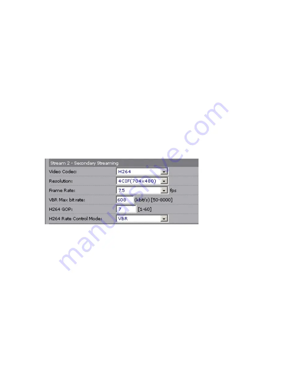
6.2.4 Stream 2 - Secondary Streaming

Secondary stream (Stream 2) is used for remote video streaming and for split-screen 
mode live video display in SRX-Pro Server.

• 

Video Codec: Set the compression mode to 

H264 (Recommended)

 or MJPEG

• 

Resolution: Set the resolution of the recorded video to one of the following:


»

720P (1280 x 720) 


»

SVGA (800 x 600)


»

4CIF (704 x 480) (Recommended)


»

VGA (640 x 480)


»

CIF (352 x 240) OR


»

“None” to disable Secondary Streaming

• 

Frame Rate: Set the frame rate for the recorded video to 1, 3, 

7.5 

(Recommended)

, 12, 15 (unavailable when Primary Stream is set to 5MP 

resolution), or 30 fps (unavailable when Primary Stream is set to 3MP or 5MP 

resolution)

• 

Max Bit Rate (for H264 codec): Set the video bit rate within a 50-8000 kbit/s 
range. 

Recommended

 Max Bit Rate value: 

608 kbit/s

Summary of Contents for Ax73RM

Page 1: ...Warnings and operation notes 3 2 Unpacking 5 3 Installation 6 4 Mounting 10 5 Connecting Ax73RM to the SRX Pro Server 17 6 Advanced Camera Setup 25 7 Specifications 53 Please read this guide carefully before you install the dome camera Keep this guide for future reference Rev 141203 ...

Page 2: ...sed or implied including but not limited to performance merchantability or fitness for any particular purpose Neither i3 International Inc nor its dealers or distributors shall be liable to any person or entity with respect to any liability loss or damage caused or alleged to have been caused directly or indirectly by this information Furthermore i3 International Inc reserves the right to revise t...

Page 3: ...hnicians to conform to all local codes and to maintain your warranty When installing your Ax73RM camera be sure to avoid excessive heat such as direct sunlight or heating appliances contaminants such as dust and smoke strong magnetic fields sources of powerful electromagnetic radiation such as radios or TV transmitters moisture and humidity areas with mechanical vibrations fluorescent lamps or obj...

Page 4: ...dry cloth to remove finger prints and dust from the dome cover Use a blower to remove dust from the lens Clean the body with a soft dry cloth If it is very dirty use a cloth dampened with a small quantity of neutral detergent then wipe dry Do not use volatile solvents such as alcohol benzene or thinners as they may damage the surface finish 1 4 Servicing To avoid electrical shock and to preserve t...

Page 5: ... x1 Use in all outdoor installations 4 Flush Mount template x1 5 Round Head Screw Tapping Type with O ring x4 6 Plastic Anchor x4 7 Long Screws for Flush Mount w Back Box installations x3 8 Standard RJ45 Connector x2 9 Security Torx bit x1 If any parts are missing or damaged contact the dealer you purchased the camera from Note Based on installation location and surface type supplied screws and an...

Page 6: ...even on an angle The dome camera is a fully integrated enclosure with camera and lens Note The six holes on top of the Ax73RM camera are not drilled all the way through for moisture control Use rubber O rings when mounting the camera 3 1 Dimensions Parts Identification 1 Camera s back box 2 Screws attaching camera module to the back box x3 silver 3 Camera module second housing 4 Tilt bracket with ...

Page 7: ... During installation sealant must be used to maintain the IP66 status 11 3 4 Side conduit hole During installation sealant must be used to maintain the IP66 status 1 Use the provided security Torx key to loosen three screws securing the dome bubble housing to camera module 8 Do not completely remove the screws from the dome bubble Lift the dome bubble off and set aside Locking arms x2 2 Next loose...

Page 8: ...Audio In Audio Out Alarm Out Alarm In Figure 3 3 1 Camera module with the back box removed I O connectors 3 3 I O Connectors Once the camera dome bubble has been removed Ax73RM input output connectors will be revealed on the camera s module including the microSD slot Factory Reset and Factory Default analog RCA video jack RJ 45 Ethernet PoE connector Audio and Alarm connectors as well as a AC24V p...

Page 9: ...iring Once disassembled prepare the camera for installation by connecting all desired inputs to the I O connectors 1 Connect Audio and Alarm wires to the 8 pin terminal block according to the wiring diagram in Figure 3 3 3 see p 8 2 Insert micro SDHC card into Micro SD card slot on the camera module See Figure 3 3 4 on p 9 for the slot location 3 Connect the camera power choose one of the two avai...

Page 10: ...ce in installations where tilt angle is 17 Lens Direction GUIDE PATTERN GUIDE PATTERN CAMERAOUTLINE CUTLINE Surface Mount Template Flush Mount Template Important Please Read Use the supplied rubber gasket for all outdoor installations Use sealant to maintain IP66 rating when installing outside It is the installer s responsibility to ensure that the mounting surface is suitable for the chosen insta...

Page 11: ...position 4 Once the desired view has been achieved replace the camera liner until it snaps back into place 5 Replace the camera dome housing on top of the camera module Use the red dots on both modules for easy alignment 6 Use the supplied Torx bit to re tighten 3 silver screws securing the dome bubble housing to the camera module Note on supplied mounting hardware Based on installation location a...

Page 12: ...ile s s s achieved replace the camera liner until it snaps back into place 6 Replace the camera dome housing on top of the camera module Use the red dots on both modules for easy alignment 7 Use the supplied Torx bit to re tighten 3 silver screws securing the dome bubble housing to the camera module 3 Remove 3 shorter silver screws s on the diagram below and fasten the camera to the back box with ...

Page 13: ...al openings are required on the mounting surface 6 Mount camera s back box to the surface 7 Use the supplied Torx bit to secure the camera module to camera s back box with the three silver screws Use the red dots on both modules for easy alignment 8 Adjust the lens angle by rotating and panning the camera lens base Do not over rotate the camera lens beyond the stop point to avoid damage to the cam...

Page 14: ...gnment 4 Adjust the lens angle by rotating and panning the camera lens base Do not over rotate the camera lens beyond the stop point to avoid damage to the camera See section 4 5 for more info Keep the camera tilt angle at 17 Tip For the ease of setup lift off the camera liner while adjusting the lens position 5 Once the desired view has been achieved replace the camera liner until it snaps into p...

Page 15: ...net Connector Note on IR LED light It is recommended to keep the camera tilt angle at 17 IR LED light reflection may interfere with the normal camera performance in installations where tilt angle is 17 Axis angle range Pan range 164 190 Horizontal rotation range 177 Tilt range 0 80 values 17 are recommended 4 6 Adjusting the Lens Position Ax73RM camera allows adjusting the field of view along thre...

Page 16: ...ole located on the camera s back box Horizontal Rotation Firmly grasp the camera lens assembly and rotate counter clockwise clockwise max 354 until satisfied with the field of view Note Over rotation past 354 will cause internal cables to become damaged disconnected or twisted Tilt Adjustment Tilt the camera lens max 80 until satisfied with the field of view Once the desired view has been achieved...

Page 17: ...ection with the Ax73RM series IP camera SRX Pro Server i3 SRX Pro Version 3 0 or higher Latest GiPi adapter is installed GiPi adapters can be downloaded from i3 Downloads web page Please contact i3 Technical Support for more information Windows XP XPe 7 Pro or 7e Internet Explorer Version 8 0 or later CPU Intel Pentium Core 2 or higher Memory 1GB or more VGA card supporting DirectX 9 0 or above Po...

Page 18: ...et Options 2 Open Privacy tab move the slider to Low or Accept All Cookies 3 Click Apply Do not close the Internet Options window Adjust Internet Security Settings 1 Open Security tab in the Internet Options window 2 If the camera operates inside of the Intranet click the Intranet icon If the camera operates outside of the Intranet click the Internet icon 3 Click Custom Level Security Settings Int...

Page 19: ...Internet Explorer window 2 Enter Ax73RM camera default IP address 192 0 0 16 3 In the Annexxus login screen enter the default camera user name i3admin and default password i3admin 4 Annexxus camera interface will be displayed in the Internet Explorer window Live video stream will be displayed on the screen If you do not see live video image on the screen call i3 International tech support for help...

Page 20: ...ro Server crossover direct connection or from the Gigabit switch to your Annexxus camera 4 Turn on your Annexxus camera 5 Locate the CD that came with your Annexxus camera and insert it in the CD ROM drive of your SRX Pro Server 6 Double click AnnexxusFinder exe file to install Annexxus Finder application Annexxus Finder application discovers all Annexxus cameras connected to your network 7 Follow...

Page 21: ...Remember Annexxus Cameras cannot share an IP address each camera requires its own unique IP address 11 Enter the default camera password i3admin in the Input Password field and click Save 12 Wait a few moments as the new IP address is being applied to your Annexxus camera Wait for the confirmation message to be displayed Click OK to close it 13 Repeat Steps 1 12 for all detected Annexxus cameras i...

Page 22: ...al com index php software downloads 2 Once the latest GiPi updater has been installed restart i3 SRX Pro Server software 3 Log In and go to the Setup IP Camera tab Explorer window Live video stream will be displayed on the screen If you see Live video image the IP address has been successfully changed Proceed to the next section Note If you do not see live video image on the screen call i3 Interna...

Page 23: ...23 Rev 141203 i3 TRNG CAMS Ax73RM indd 4 Click the Search button to display connected Annexxus cameras 5 Select the detected camera in the list and click Select ...

Page 24: ... to the SRX Pro video channel in the Ch In column Your Annexxus camera is now connected to SRX Pro Server and is ready to record You may change resolution and frame rate for the Annexxus camera in the IP Camera tab menu or you may choose to configure the camera s advanced settings see the following section Tip In SRX Pro Server ensure that Motion Setup Schedule Setup and Storage setup tabs are cor...

Page 25: ...up IP Camera tab select the camera in the list of added IP cameras and click the Advanced Setup button The password window will be displayed Enter the default camera User Name i3admin and default Password i3admin Camera s user interface will be displayed in the Internet Explorer window C A B Camera s User Interface ...

Page 26: ...o G 711 A law or G 711 µ law G 711u Audio In Volume Set Audio In volume to Low Middle or High Audio Out Turn Audio Out ON or OFF Audio Out Volume Set Audio Out volume to Low Middle or High Click the Setup button to access Annexxus camera Setup features A Control Panel Live Mode Search Mode Setup Mode B Camera Adjustments panels PTZ Controls Video Adjustments Audio Settings C Live Video viewing are...

Page 27: ...ing adjustments remember to click the Save button It is recommended to make changes to one field at a time and save after each setting adjustment 6 1 1 Camera Settings Primary Streaming only Note To configure sub stream Secondary Streaming click the Advance Setup button Secondary Streaming is used by SRX Pro Server for faster live video display and remote streaming Camera Name The name of the came...

Page 28: ... a variable bit rate video stream however the video quality will remain constant resulting in high quality video images Network infrastructure must be able to provide the set bandwidth to account for bit rate variations CBR Constant Bit Rate This setting will produce a constant bit rate video stream at the cost of video quality The quality may deteriorate considerably when motion is detected This ...

Page 29: ...setup tabs Video Setup tab is displayed by default 6 2 2 Camera Settings Camera Name The name of the camera will be displayed at the top of the Internet browser page TV System NTSC or PAL To change the setting access System setup tab Mirror Flips the video image The options for mirror are OFF Do not use this feature FLIP flip images vertically upside down MIRROR flip images horizontally left to ri...

Page 30: ... faster remote video streaming This combination of recommended video settings conserves and prolongs video storage while taking advantage of high resolution video images Recommended Video Settings for the Primary Stream Stream 1 Video Codec H264 Resolution Highest resolution offered by the camera Frame Rate 1 3 fps based on customer preference and camera s available frame rate options Recommended ...

Page 31: ...tion Set the resolution of the recorded video to one of the following 2592 x 1944 5MP Recommended QXGA 2048 x 1536 3MP 1080P 1920 1080 SXGA 1280 960 720P 1280 720 SVGA 800 600 Frame Rate Set the frame rate for the recorded video to 1 3 Recommended 7 5 12 15 unavailable with 5MP resolution or 30 fps unavailable with 3MP and 5MP resolution Max Bit Rate for H264 codec Set the video bit rate within a ...

Page 32: ...th limited bandwidth Quality for MJPEG codec only HIGH MID LOW 6 2 4 Stream 2 Secondary Streaming Secondary stream Stream 2 is used for remote video streaming and for split screen mode live video display in SRX Pro Server Video Codec Set the compression mode to H264 Recommended or MJPEG Resolution Set the resolution of the recorded video to one of the following 720P 1280 x 720 SVGA 800 x 600 4CIF ...

Page 33: ...on Quality for MJPEG codec only HIGH MID LOW 6 2 5 Stream 3 Third Streaming Third streaming is not being utilized by SRX Pro Server If using exclusively with SRX Pro Server disable Third Stream by selecting None from the Resolution drop down menu If also recording video to SMTP or FTP Server directly from the camera configure Third Steaming as follows Video Codec Set the compression mode to MJPEG ...

Page 34: ... and blue in the image Values can be set from 0 255 Brightness adjust the image brightness level Values range from 0 to 100 Contrast adjust the image contrast level Values range from 0 to 100 Saturation adjust the image saturation level Values range from 0 to 100 Sharpness adjust the image sharpness level Values range from 0 to 15 Hue adjust the image hue Values range from 0 to 15 After making any...

Page 35: ...e lens focus Ax73RM s motorized lens will re focus the lens automatically but focus can also be adjusted manually if needed When in Live mode use Focus Near Far icons on the PTZ Controls panel to controls lens focus manually Reset the camera to the default Zoom position Auto Focus Press Calibrate to return the camera s lens to its default focal length and auto focus 6 4 Alarm Motion optional Alarm...

Page 36: ...tected by the camera select Alarm Output 1 Then set Digital Output to ON in the Alarm section below To disable Alarm Output select None See Section 3 3 I O Connectors for information on how to connect an Alarm Output to the camera Draw the motion detection area in the Preview screen Position your mouse cursor over the Preview window press and hold the left mouse button While holding down the left ...

Page 37: ... to connect an Alarm Output to the camera Digital Output must be set to ON to be used in conjunction with edge motion detection Output Active Type Set to High or Low High is equivalent to Normally Open relay Low is equivalent to Normally Closed relay Duration Set the Digital Output Control Duration Dwell time to 1 5 or 10 seconds After making any setting adjustments remember to click the Save butt...

Page 38: ...t needs to be concealed 4 Release the mouse button The privacy area rectangle will be shaded purple in the Preview window 5 If you are not satisfied with the size or positioning of the privacy zone repeat steps 2 4 to re draw it 6 Click the Apply button 7 Repeat Steps 1 6 for additional Privacy Zones if using After making any setting adjustments remember to click the Save button to save any change...

Page 39: ...isc EV Set exposure value between 2 and 2 Higher values produce brighter images Day Night Set the Day Night setting to AUTO COLOR or BW Noise Reduction Set the Noise Reduction value The values range from 0 to 255 BLC When parts of the environment are poorly lit BLC can be configured to compensate for inadequate lighting conditions To configure the individual areas that will receive compensation se...

Page 40: ... to 5 or 10 seconds If Motion recording is selected set the video recording duration in seconds after the motion has stopped SD Card Usage Displays the percentage of disk space used for video recording on the microSD card SD card Format Click the SD Format button to erase all data from microSD card Click OK in the confirmation window then wait for the Format Complete message window and click OK to...

Page 41: ...n Detection must be Enabled and the Motion Detection area must be highlighted in the Preview window of the camera s Alarm Motion tab 2 microSD card must be inserted into the microSD card slot on the camera 3 SD Card Record Conditions must be set to Motion Network Loss Recording To record video to the microSD card whenever network connection to the SRX Pro Server is lost the following conditions mu...

Page 42: ... MJPEG video streams can be used with SMTP FTP recording options Set the Third Stream Stream 3 option to MJPEG Video Codec in Video setup tab 6 8 1 SMTP Recording Note Only MJPEG video streams can be used with the SMTP recording options Set the Third Stream Stream 3 option to MJPEG Video Codec in Video setup tab SMTP Server SMTP Record Condition Set to ALARM or MOTION to enable this setting SMTP S...

Page 43: ...must be Enabled and configured in the camera s Alarm Motion tab 3 Motion Detection must be Enabled and the Motion Detection area must be highlighted in the Preview window of the camera s Alarm Motion tab 4 SMTP Record Condition must be set to either ALARM or MOTION in the Network Recording tab 5 Email recipient s must be configured in the Network Recording tab Subject Enter the email subject Messa...

Page 44: ...P Port Note This feature works in conjunction with MJPEG codec only Set Third Stream to MJPEG in order to record to an FTP Server Scheduled Recording Table Set the recording schedule type for each day of the week OFF to disable ALL DAY SCHEDULE 1 or SCHEDULE 2 Schedules 1 and 2 are configured directly below Scheduled Recording Settings Schedule 1 and Schedule 2 Set the Start Time and End Time for ...

Page 45: ...ideo will be pre pended to the video clip Recording Frame Set the video frame rate for the video that immediately follows the triggered motion or alarm 1 60 frames per second Recording Cycle Set the video recording length in sec that immediately follows the triggered motion or alarm 1 120 seconds 2 minutes File Name Set the default video file name Server Path Set the FTP Server path where the vide...

Page 46: ...he network automatically assign an IP address to the camera IP Address Manually enter the camera s IP address here This option should NOT be used if DHCP is enabled Subnet Mask Manually enter the camera s Subnet Mask here This option should NOT be used if DHCP is enabled Default Gateway Provide the IP address of the network s router if necessary Contact your network administrator for this informat...

Page 47: ...nside the camera for remote video retrieval FTP Set to ON or OFF Must be set to ON to retrieve video recorded to microSD card remotely FTP Login ID FTP Password Enter FTP login credentials Max Simultaneous Connection Enter the maximum number of remote FTP Client connections accepted by the microSD card Note this number does not limit the number of remote Internet Explorer connections To view video...

Page 48: ... Can be set to ON to show or OFF to hide the camera s current Date and Time set in System setup tab After making any setting adjustments remember to click the Save button to save any changes made 6 10 User Management Setup User Management tab displays the list of users that have access to the Annexxus camera The username and password from this setup tab are used when connecting the camera to SRX P...

Page 49: ...e Modify User area 3 To change the account password enter the new password in the Password field and Confirm Password fields of the Modify User area 4 To change permission type select either Administrator or Viewer in the Permission drop down menu 5 Click Update User button to apply changes 6 Click OK in the confirmation message Reminder Whenever a change is made to the Annexxus camera user in the...

Page 50: ... currently doesn t match your local standard System Information Update Firmware All Annexxus series cameras are sold with the most recent version of the firmware already installed If in the future firmware updates are released you can update your camera s firmware by first downloading the firmware file from i3 International s website or FTP site After downloading firmware file click the Browse but...

Page 51: ... Yes Click Hard Factory Reset to return all camera settings including IP address to factory defaults After clicking a pop up will appear asking you to confirm Click Yes Note Your Network Camera s default IP address is 192 0 0 16 and the default Subnet mask address is 255 255 255 0 System Information Configuration Settings Click Export File to export your camera s settings If you have multiple came...

Page 52: ...Rev 141203 6 10 Logs Logs setup tab displays camera event log records Clean Logs Erases all log records Refresh Logs Update the list of current event logs Download Logs Click to export all event log records into a text log file ...

Page 53: ...d separately Alarm In Out Alarm In x1 Alarm Out x1 Back Light Compensation Off On 7 Area Selectable Network Specifications Video Streaming and Compression Method Triple Streaming H 264 Motion JPEG Frame Rate NTSC 1080P 1920x1080 30fps 3M 2048x1536 15 fps 5M 2592x1944 12 fps PAL 1080P 1920x1080 25fps 3M 2048x1536 15 fps 5M 2592x1944 12 fps Resolutions 5M 2592x1944 3M 2048x1536 1080P 1920x1080 SXGA ...

Page 54: ...ock Alarm in out 8 pin removable terminal block IR IR Distance 15M IR LED 24 pcs IR Wavelength 850 nm Power Supply Power Requirement PoE IEEE 802 3af class 0 AC 24V Power Consumption max PoE 11 5W AC24V 26W Temperature Control On board heating device by PoE AC24V Defog Control Patented thermal defog dome bubble by AC24V Surge Protection EN55024 certified Environment Operating Temperature 40º C 50º...

Page 55: ...i3 INTERNATIONAL INC 1 866 840 0004 www i3international com Canada 780 Birchmount Road Unit 16 Scarborough ON M1K 5H4 U S A 1967 Wehrle Drive Suite 1 PMB 034 Buffalo NY 14221 ...

Reviews: