background image

5

10 USB-to-PC

Connects this USB-B to PC to provide 2 functions:
1. USB audio device. (An USB audio device will be
detected when it is attached to PC in Windows OS)
2. Virtual 4-port USB Hub for remote USB devices.

11 HDMI IN

Connects to HDMI Source. For DVI source, you
may need a HDMI-to-DVI adapter cable.

12 IR Blaster

(optional)

Connects to external IR LED.

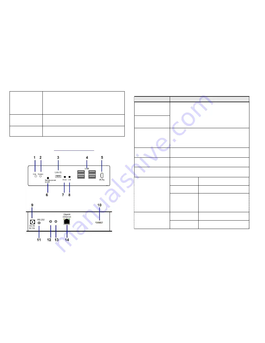
Panel View

CIP900-IP-R Receiver

6

No.  Component

Description

1   Green LED

(Power/Link status)

Green Blinking/Red Off:

System is starting up.

Green On/Red Blinking:

 Linking or waiting

HDMI input.

Green On/Red On:

 Connection established.

2   Red LED

(System status)

3   Link ID

4 bit DIP switch for 16 ID settings. To make
Transmitter/Receiver as a pair or group, the
transmitter and receiver must be set with the
same Link ID.

4   USB Host

For remote USB devices, such as USB
KB/Mouse, storage, audio, …

5  IR Rx (optional) 

Remote Universal IR receiver.

6   Remote Power

On/Off (optional)

Button for Remote PC Power On/Off function.

7   Mode button

Short press

Switch to Video or Graphic
mode

Long press

(*)Anti-Dither Mode

Press and Hold
at Power ON
until Green LED
blinking

Get and Use this Receiver’s

EDID as the system EDID

(update CIP900-IP-T EDID)

8   Link button

Short press

Link/Unlink

Long press

This CIP900-IP-R will get the
USB access right.

Summary of Contents for CIP900-IP-TR

Page 1: ...ects with PC or any device with HDMI source The CIP900 IP R receiver connects to HDMI display speaker microphone USB devices Keyboard Mouse Storage and RS232 devices It based on the standard Ethernet IP network all Gigabit or Fiber LAN switch HUB can be used for inter connection Package Includes 1 CIP900 IP T Transmitter Unit 1 CIP900 IP R Receiver Unit 1 HDMI HDMI or HDMI DVI cable 2 5V DC Power ...

Page 2: ...ON until Green LED blinking Get and Use EDID from Loop out monitor 3 Red LED System status Green Blinking Red Off System is starting up Green On Red Blinking Linking or waiting HDMI input source Green On Red On Connection established 4 Green LED Power Link status 5 Remote Power On Off optional Connects to PC motherboard for Remote Power On Off 6 Link ID 4 bit DIP switch for 16 ID settings To make ...

Page 3: ...DMI input Green On Red On Connection established 2 Red LED System status 3 Link ID 4 bit DIP switch for 16 ID settings To make Transmitter Receiver as a pair or group the transmitter and receiver must be set with the same Link ID 4 USB Host For remote USB devices such as USB KB Mouse storage audio 5 IR Rx optional Remote Universal IR receiver 6 Remote Power On Off optional Button for Remote PC Pow...

Page 4: ...P T and CIP900 IP R are having the same setting They make pair or group according to this Link ID setting 2 Attach your HDMI display to the CIP900 IP R HDMI Out port 3 Power on the CIP900 IP R an AVExtender logo will be displayed If not then something wrong either on the CIP900 IP R or HDMI cable or HDMI display 4 You can connect multiple CIP900 IP R and multiple CIP900 IP T units to your Gigabit ...

Page 5: ...IP900 IP T to the Factory default setting Press and Hold the Button 1 then Power ON until Green and Red LED blinking 2 To Use the CIP900 IP T Loop out monitor EDID Press and Hold the Button 2 then Power ON until Green LED blinking 3 To update the CIP900 IP R EDID Press and Hold the Mode button then Power ON until Green LED blinking 4 To Reset the CIP900 IP R to the Factory default setting Press an...

Page 6: ...P900 IP T 5 2 3 8 7 6 4 1 9 12 Infrared Control optional This function has been designed to transmit remote control signal from the location of CIP900 IP R to the AV sources 1 Connects the supplied IR blaster cable to the IR blaster socket at the rear panel of the CIP900 IP T Transmitter Please check if the LED on the IR blaster is rightly positioned in the front of the AV sources 2 Make sure your...

Reviews: