11
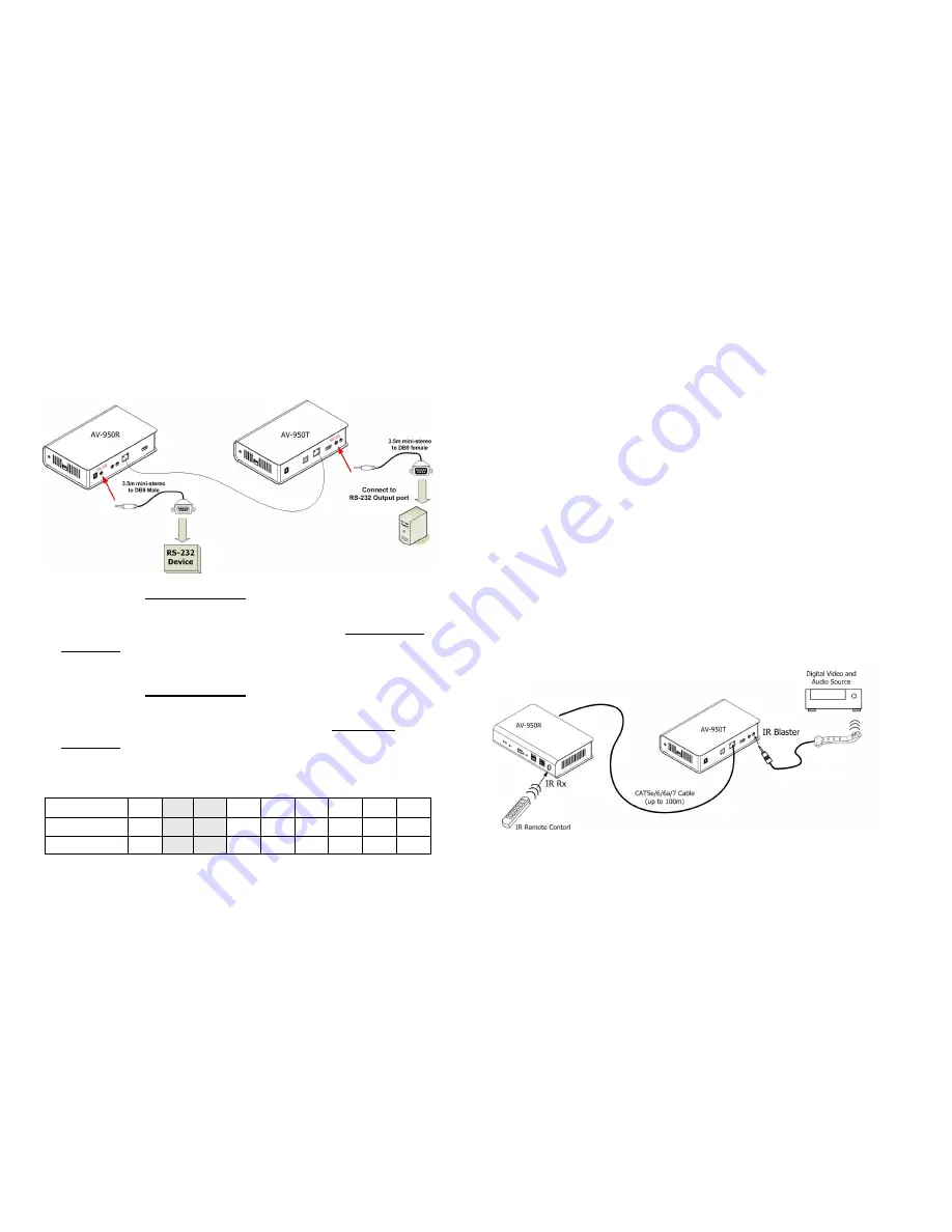
RS-232 Control (optional)
This function has been designed to remote access and control of
any RS-232 device.
1.
Connects the 3.5m mini-stereo plug of the supplied RS-232
cable to the
[RS-232]
socket at the rear panel of the
CIP900-IP-T Transmitter, and then connect the DB9 Female
connector of the supplied RS-232 cable to the [RS-232] output
port of your PC.
2.
Connects the 3.5m mini-stereo plug of the supplied RS-232
cable to the
[RS-232]
socket at the rear panel of the
CIP900-IP-R Receiver, and then connect the DB9 Male
connector of the supplied RS-232 cable to the RS-232 device.
Pin Assignments
Signal
-NC- TxD RxD -NC- -NC- -NC- -NC- -NC- -NC-
CIP900-IP-R
5
3
2
7
8
4
6
1
9
CIP900-IP-T
5
2
3
8
7
6
4
1
9
12
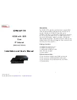
Infrared Control (optional)
This function has been designed to transmit remote control signal
from the location of CIP900-IP-R to the AV sources.
1.
Connects the supplied IR blaster cable to the
[IR blaster]
socket at the rear panel of the CIP900-IP-T Transmitter.
Please check if the LED on the IR blaster is rightly positioned
in the front of the AV sources.
2.
Make sure your infrared remote controller is able to align the
CIP900-IP-R
[IR Rx]
port. When you press any key on any
remote controller, the CIP900-IP-R receives the IR signal and
transmits it to the CIP900-IP-T. Then the IR signal is delivered
to the IR receiver of your AV sources device through the LED
on the IR blaster cable.
3.
To work properly, the LED of the IR blaster cable must be
facing the IR receiver of your Windows Media Center Edition
PC, TV tuner card or DVD player.


