background image

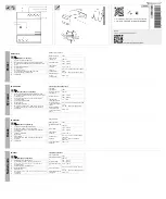
Fig. 2-2 Standard circuit diagram / 그림 2-2 표준 내부 회로도

진공차단기 취급설명서

>>

7

VCB

|

HVF Series

Note - Extended circuit spec & connection line number are

defined by user's request.

- For the AC control circuit, the rectifier should be

attached on the standard circuit.

- Standard contacts can be insufficient on the request of

the extended circuit.

- In case of 1 option applied, the numbers are 21, 22 for

A, B Jack and 3, 8 for C, D Jack.

※ 주의

- 추가 회로 및 접속은 고객 요구에 따라 변경될 수 있습니다.
- AC 제어전원에 대해서는 정류기가 추가됩니다.
- 추가 회로 요청 시, 표준 접점이 부족할 수도 있습니다.
- 전기적 Option을 1개 적용 시, A, B Jack은 21, 22번으로

인출을 하고, C, D Jack은 3, 8번으로 인출합니다.  

M1

Motor operating mechanism

K1

Anti-pumping contactor

R1

Resistor

X0

Plug Connector

Y1

Open solenoid

Y2

2nd open solenoid

Y4

C.T. operated release

Y7

Under-voltage release

Y9

Closing solenoid

S1

Auxiliary switch

S3

Limit switch (K1 Control)

Limit switch supplied with the lockout

S5

(Prevents closing by electrical means when

Lock-out effective)

S6, S7

Cutout switches

S21, S22

Limit switches 

(Interrupt motor circuit after spring charged)

S41, S42

Position switch (spring charged status signal)

Summary of Contents for HVF Series

Page 1: ...it breaker This instruction manual should be applied only to HVF Series Vacuum Circuit Breakers This instruction manual does not include all items regarding installation and maintenance procedures For...

Page 2: ...ould be accessible to those persons at all times Signal Words Signal words used in this instruction manual are DANGER WARNING and CAUTION in descending order of urgency Indicates an imminently hazardo...

Page 3: ...touch the main and control circuit while the product is in operation The hazardous voltage can cause electric shocks Do not let the product stay in the DISCONNECTION position with UNLOCK state If the...

Page 4: ...stalling the Breaker 11 3 1 Unloading and Storage 3 2 Unpacking 3 3 Inspection After Unpacking 3 4 Installation 3 5 Inspection Before Operation 3 6 Manual Operation 4 Structure and Operation 13 4 1 Co...

Page 5: ...1141 C HVF1151 D HVF2141 C HVF2151 D HVF3141 C HVF3151 D HVF6111 F HVF6141 F HVF1142 C HVF1152 D HVF1162 D HVF1172 F HVF2142 C HVF2152 D HVF2162 D HVF2172 F HVF3142 C HVF3152 D HVF3162 D F HVF6112 F H...

Page 6: ...xt close open operation without delay Consideration of site altitude If the site altitude is higher than 1000 m dielectric strength of the breaker will be reduced according to the altitude Therefore t...

Page 7: ...B Jack and 3 8 for C D Jack AC Option 1 A B Jack 21 22 C D Jack 3 8 M1 Motor operating mechanism K1 Anti pumping contactor R1 Resistor X0 Plug Connector Y1 Open solenoid Y2 2nd open solenoid Y4 C T op...

Page 8: ...he contact pressure spring is compressed properly to maintain sufficient contact pressure on the moving contact of the vacuum interrupters while the breaker is in the closed position and the tripping...

Page 9: ...e used as AC power supply connecting to the motor or closing circuit 2 8 AC Ry B1 B2 9 VCB HVF Series Fig 2 4 Condenser trip device 2 4 Fig 2 5 Circuit diagram of condenser trip device 2 5 This device...

Page 10: ...g the screw down as shown in Fig 2 7 2 10 2nd Open Solenoid Y2 The 2nd trip solenoid Y2 can be attached to the HYUNDAI HVF circuit breaker putting aside the 1st trip solenoid Y1 so that the circuit br...

Page 11: ...any damage or missing materials 3 Check all accessories and spares supplied Also check to see if these parts are damaged 3 4 Installation Before installing the circuit breaker into the switchgear che...

Page 12: ...ress the OPEN button And be sure to check that the breaker is opened and the CLOSE OPEN indicator displays open 4 Finally check that no tools and materials are left near the breaker Bus bar 3 5 1 2 3...

Page 13: ...Indicator 21 Closing Button 22 Trip Button 23 Name Plate 24 Hole for the charging handle 31 Motor 32 Closing Solenoid 33 Trip Solenoid 34 Limit Switch S3 S21 S22 35 Anti Pumping Contact K1 36 Auxilia...

Page 14: ...essed to insure sufficient contact pressure on the moving contact while the breaker is in the closed position and the tripping spring 13 is compressed for the opening operation 3 Recharging After the...

Page 15: ...disconnection or test position At this time push down the interlock lever fully for easy insertion Check that the wheels of the breaker are inserted into the cradle as fig 4 8 3 Insertion to the conne...

Page 16: ...the breaker is opened insert the crank handle in the hole and push the interlock lever down fully Then push the crank handle down against the breaker so that the breaker goes to the disconnection pos...

Page 17: ...e in the hole to draw in and out Rotate handle about 50 times counterclockwise If operator pulls the center handle out interlock will be released and the breaker will be fully separated from cradle 3...

Page 18: ...ition After lifting the center handle the operator can push the breaker to the cradle until it makes a locked sound 3 Insertion into the connection position Same as the SF GS type method 4 Withdrawing...

Page 19: ...ocker to the unlock state and pull the breaker out slowly The Head of Fixing Screw Improper operation of the breaker can cause product damage The breaker can be withdrawn if the head of the fixing scr...

Page 20: ...year a general visual inspection is to be carried out The outer insulation parts should be wiped with a rag more frequently if the breakers are exposed to dust HVF 5 1 5 1 Failure to maintain the equ...

Page 21: ...re insulation resistance between phases and between pole earth with 1000 V megger if the measured value is less than 500 M check the cause 2 Check insulation resistance between control circuit and ear...

Page 22: ...Motor switch off Motor will not run Spring charged Closing spring not charged Breaker closed Breaker is not in proper position No electrical close signal Breaker open No electrical open signal Check...

Page 23: ...th to prevent any accumulation of dust or dirt Avoid any lubricant on insulation or other electrical parts Moving parts should then be moved slightly to let the grease penetrate and become properly di...

Page 24: ...01746 HVS01746 HVS01747 HVS01753 HVS01753 HVS01753 HVS01753 HVS01726 HVS01745 HVS01745 HVS01745 HVS01746 HVS01746 HVS01747 20 20 20 20 20 20 20 20 20 20 28 28 28 28 28 28 28 28 28 28 38 38 38 38 38 38...

Page 25: ...S02421 HVS02421 HVS02435 HVS03626 HVS03626 HVS03640 HVS03640 HVS03640 HVS01750 HVS01750 HVS01750 HVS01746 HVS03640 HVS03640 HVS03640 HVS03642 HVS03642 HVS03642 38 50 50 50 50 70 70 70 70 70 19 19 36 3...

Page 26: ...26 Vacuum Circuit Breaker Instruction Manual Maintenance Recording Maintenance Recording Sheet Date Signature Remarks Cost Free Engineer Service Agent The Substance of Service...

Page 27: ...27 VCB HVF Series Memo...

Page 28: ...Yurakucho Denki Bldg 1 7 1 Yuraku cho Chiyoda ku Tokyo 100 0006 Japan Tel 81 3 3211 4792 Fax 81 3 3216 0728 Osaka I Room 5th Floor Nagahori Plaza Bldg 2 4 8 Minami Senba Chuo ku Osaka 542 0081 Japan T...

Reviews: