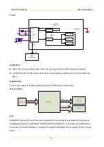


VHF (136-174 MHz)
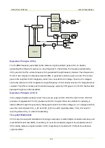
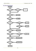
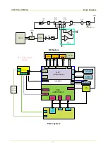
Troubleshooting Flow Chart
29
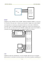
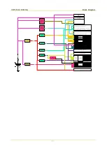
[2] For low power, VGG: 1.8–2.1 V; for high power, VGG: 2.4–2.8 V.
[3] For low power, TV/APC: 1-1.3 V; for high power, TV/APC: 1.8-2.1 V.
[4] TX_En: about 3.3 V.
[5] 5VA_TX: about 5 V.
[6] High power: about 4.2 W; low power: about 1.2 W.
[7] Start-up voltage of D7001: about 0.7 V. The low-pass coil must be soldered appropriately and remain
in good condition. The spring plate for the antenna must well fit the antenna connector.
[8] The match components must not be soldered inapproptiately or damaged.
[9] Vdd: about 7.3 V; for low power, Vgg: 1-1.2 V; for high power, Vgg: 1.35-1.55 V.
[10] Vdd: about 7.3 V; for low power, Vgg: 1.8-2.1 V; for high power, Vgg: 2.4-2.8 V.
[11] Vc: about 4.8 V; Vb: about 1.4 V; Ve: about 1.1 V.
[12] Vc: about 4.7 V; Vb: about 0.7 V; Ve: 0V. Start-up voltage of D9007: about 0.7 V.
Summary of Contents for PD502
Page 1: ...PORTABLE...
Page 5: ...VHF 136 174 MHz...
Page 13: ...VHF 136 174 MHz Exploded View and Packaging Guide 7 3 2 Packaging Guide...
Page 18: ...VHF 136 174 MHz Circuit Description 12...
Page 43: ...PCB 3 9 PCB VHF 136 174 MHz...
Page 44: ...PCB 3 VHF 136 174 MHz...
Page 71: ...UHF1 400 470 MHz...
Page 79: ...UHF1 400 470MHz Exploded View and Packaging Guide 7 3 2 Packaging Guide...
Page 84: ...UHF1 400 470MHz Circuit Description 12...
Page 108: ...UHF1 400 470MHz PCB 36 9 PCB...
Page 109: ...UHF1 400 470MHz PCB 37...
Page 136: ...1616300000260 2014 03 17 L07157 4...