


VHF (136-174 MHz)
Circuit Description
18
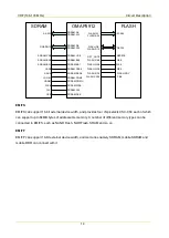
MCSI1.SYNC(W8)
MCSI1.CLK(M15)
MCSI1.DOUT(W14)
U1002
OMAP5912
CS
SKY72310
SCK
Data
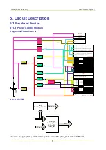
5.1.3
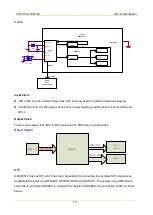
Audio Module
Audio Diagram
The audio module is mainly for audio input and output. TLV320AIC29 is used as the audio codec to
convert and process audio signal and digital signal. The audio amplifier TDA2822 is used to amplify the
analog audio signal.
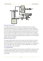
DSP processes digital signal (including audio signal encoding/decoding, digital signal decoding, and
digital audio signal processing). AD9864 converts and processes the RF IF signal, and sends the
undemodulated serial digital signal to the DSP for processing. Then TLV5614 converts the digital signal
output by DSP to analog signal.
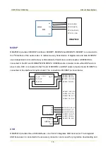
TLV320AIC29
MIC Input
IIS
SPI
OMAP5912
Process via DSP
McBSP1
uWire
SPI(CS2)
AD9864
TLV5614
DAC
M
cB
SP
2
SPI
SSI
SSI
RX
TX
APA
TD2822
Speaker
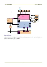
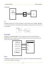
Diagram of Signal Flow
The microphone converts the audio signal into electrical signal, which is then amplified by PGA of the
codec and sent to ADC of the codec for sampling. After digital audio processing, the signal is output to
Summary of Contents for PD502
Page 1: ...PORTABLE...
Page 5: ...VHF 136 174 MHz...
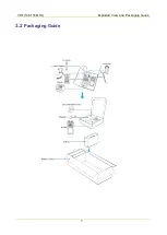
Page 13: ...VHF 136 174 MHz Exploded View and Packaging Guide 7 3 2 Packaging Guide...
Page 18: ...VHF 136 174 MHz Circuit Description 12...
Page 43: ...PCB 3 9 PCB VHF 136 174 MHz...
Page 44: ...PCB 3 VHF 136 174 MHz...
Page 71: ...UHF1 400 470 MHz...
Page 79: ...UHF1 400 470MHz Exploded View and Packaging Guide 7 3 2 Packaging Guide...
Page 84: ...UHF1 400 470MHz Circuit Description 12...
Page 108: ...UHF1 400 470MHz PCB 36 9 PCB...
Page 109: ...UHF1 400 470MHz PCB 37...
Page 136: ...1616300000260 2014 03 17 L07157 4...