- 13 -
Belt & Pulley Drive Installation
▫
Pulley Driven
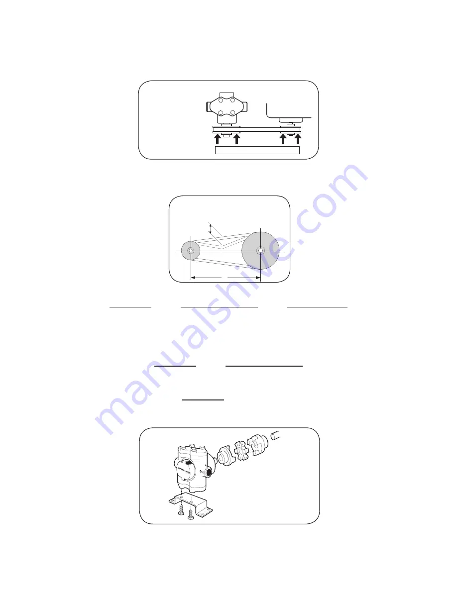
- Mount pulleys as close to pump and motor engine shaft bearings as possible. Check alignment
with a straight edge as shown in Fig. 1.
▫
Make sure that belt has proper tension. (Too much tension will cause bearing wear; too little will cause slippage.) See Fig. 2.
▫
Check with belt and pulley sources for specific recommendation. To figure proper diameter of pump pulley, multiply
motor/engine rpm by diameter of the motor/engine pulley and divide that figure by desired pump speed. Belt and
pulley drive systems are typically used to reduce pump speed. For determining proper pulley sizes, use the formula
below as a guideline and use “A” or “B” section belts.
Motor RPM
=
Flow (@ Rated Speed)
=
Pump Pulley Dia.
Pump RPM
Flow (Desired)
Motor Pulley Dia.
Example:
•
Use a 1725 RPM electric motor to drive a pump at 950 RPM.
• Typically, a pulley diameter on the motor is 3.4 inches. The pump pulley diameter can be determined from the formula
above:
1725 RPM
=
Pump Pulley Dia.
950 RPM
3.4”
• Solving this equation for the Pump Pulley diameter yields:
1725 RPM
x 3.4” = 6.2”
950 RPM
•
Refer to pump performance charts to determine desired speed and to obtain desired maximum flow.
• Flexible Coupling
- To install couplings, slide coupling ends onto motor or engine and pump shafts as far as possible.
Mount engine/motor and pump on base. Shim up pump or power to align shafts. Leave enough room between shaft
ends to install center disc. When aligned, slide ends over disc. Select couplings rated twice required horsepower
when using motor; three times when using gas engine.
d
L
Push the belt midway between the pulleys, check
the deflection (d) and adjust:
d = 0.016 x L
Four points of
contact indicate
alignment.
NOTE: Pump may
be mounted in other
orientations with
respect to the motor
or engine.
CAUTION:
For safety, always install a
shield over rotating shafts
and couplings.
Figure 1
Figure 2
Summary of Contents for 5315C Series
Page 22: ...Notes...


