background image

3-17

Service Manual

M

AINTENANCE

Figure 3-5.1   Wiring Harness Diagram, 115/230 Volt

7-98

Summary of Contents for powermax 350

Page 1: ...Plasma Arc Cutting System Service Manual 802920 Revision 1 EN50199 EN50192 ...

Page 2: ...ew Hampshire 03755 5010 Tel 603 643 3441 Fax 603 643 5352 http www hypertherm com Copyright 1998 Hypertherm Inc All Rights Reserved Revision 1 July 1998 Hypertherm HyDefinition Powermax and LongLife are trademarks of Hypertherm Inc and may be registered in the United States and or other countries ...

Page 3: ...l 65 841 2490 Fax 65 841 2489 Technical Service Japan Shinjuku Park Tower 30th Floor 3 7 1 Nishi Shinjuku Shinjuku ku Tokyo 163 1030 Japan 81 03 5326 3142 Tel 81 03 5326 3001 Fax Hypertherm UK Ltd 9 Berkeley Court Manor Park Runcorn Cheshire England WA7 1TQ 44 1928 579 074 Tel 44 1928 579 604 Fax France 15 Impasse des Rosiers 95610 Eragny France 33 1 30 37 15 28 Tel 33 1 30 37 15 79 Fax Hypertherm...

Page 4: ...ection to the workpiece but in some countries where direct connection is not permitted the bonding should be achieved by suitable capacitances selected according to national regulations Note The cutting circuit may or may not be earthed for safety reasons Changing the earthing arrangements should only be au thorized by a person who is competent to assess whether the changes will increase the risk ...

Page 5: ...actured by Hypertherm or manufactured by a person other than Hypertherm not in strict conformity with Hypertherm s specifications and in cases of designs processes formulae or combinations not developed or purported to be developed by Hypertherm Hypertherm will defend or settle at its own expense any suit or proceeding brought against you alleging that the use of the Hypertherm product alone and n...

Page 6: ...rité 1a 2 Le coupage peut provoquer un incendie ou une explosion 1a 2 Les chocs électriques peuvent être fatals 1a 3 Le coupage peut produire des vapeurs toxiques 1a 3 L arc plasma peut provoquer des blessures ou des brûlures 1a 4 Mise à la masse et à la terre 1a 4 Les rayons de l arc peuvent brûler les yeux et la peau 1a 4 Sécurité des bouteilles de gaz comprimé 1a 5 Les bouteilles de gaz comprim...

Page 7: ... 2 1 Functional Block Diagram 115 230 Volt Unit 3 4 Figure 3 2 2 Functional Block Diagram 200 Volt Unit 3 6 Figure 3 3 Trouble LED Indicators 3 8 Figure 3 4 1 Wiring Diagram 115 230 Volt Unit 3 12 Figure 3 4 2 Wiring Diagram 200 Volt Unit 3 14 Figure 3 5 1 Wiring Harness Diagram 115 230 Volt Unit 3 16 Figure 3 5 2 Wiring Harness Diagram 200 Volt Unit 3 18 Figure 3 6 PAC110 Torch Repair 3 21 Figure...

Page 8: ...n Kill 1 3 Cutting Can Produce Toxic Fumes 1 3 A Plasma Arc Can Cause Injury and Burns 1 4 Arc Rays Can Burn Eyes and Skin 1 4 Grounding Safety 1 4 Compressed Gas Equipment Safety 1 5 Gas Cylinders Can Explode If Damaged 1 5 Noise Can Damage Hearing 1 5 Pacemaker and Hearing Aid Operation 1 5 A Plasma Arc Can Damage Frozen Pipes 1 5 Additional Safety Information 1 5 Warning Label 1 6 ...

Page 9: ... sure the area is safe before doing any cutting Keep a fire extinguisher nearby Remove all flammables within 35 feet 10 m of the cutting area Quench hot metal or allow it to cool before handling or before letting it touch combustible materials Never cut containers with potentially flammable materials inside they must be emptied and properly cleaned first Ventilate potentially flammable atmospheres...

Page 10: ... on the workbench with the work cable attached during the cutting process Before checking cleaning or changing torch parts disconnect the main power or unplug the power supply Never bypass or shortcut the safety interlocks Before removing any power supply or system enclosure cover disconnect electrical input power Wait 5 minutes after disconnecting the main power to allow capacitors to discharge N...

Page 11: ...ant clothing to cover all exposed areas Cuffless trousers to prevent entry of sparks and slag Remove any combustibles such as a butane lighter or matches from your pockets before cutting Cutting Area Prepare the cutting area to reduce reflection and transmission of ultraviolet light Paint walls and other surfaces with dark colors to reduce reflection Use protective screens or barriers to protect o...

Page 12: ...s possible to the work cable Do not wrap or drape the torch lead or work cable around your body Keep as far away from the power supply as possible PACEMAKER AND HEARING AID OPERATION ADDITIONAL SAFETY INFORMATION 1 ANSI Standard Z49 1 Safety in Welding and Cutting American Welding Society 550 LeJeune Road P O Box 351020 Miami FL 33135 2 ANSI Standard Z49 2 Fire Prevention in the Use of Cutting and...

Page 13: ...cutting path 2 3 Wear complete body protection 3 Electric shock from torch or wiring can kill Protect yourself from electric shock 3 1 Wear insulating gloves Do not wear wet or damaged gloves 3 2 Insulate yourself from work and ground 3 3 Disconnect input plug or power before working on machine 4 Breathing cutting fumes can be hazardous to your health 4 1 Keep your head out of the fumes 4 2 Use fo...

Page 14: ...T ÊTRE FATALS 1a 3 LE COUPAGE PEUT PRODUIRE DES VAPEURS TOXIQUES 1a 3 L ARC PLASMA PEUT PROVOQUER DES BLESSURES OU DES BRÛLURES 1a 4 LES RAYONS DE L ARC PEUVENT BRÛLER LES YEUX ET LA PEAU 1a 4 MISE À LA MASSE ET À LA TERRE 1a 4 SÉCURITÉ DES BOUTEILLES DE GAZ COMPRIMÉ 1a 5 LES BOUTEILLES DE GAZ COMPRIMÉ PEUVENT EXPLOSER EN CAS DE DOMMAGES 1a 5 LE BRUIT PEUT PROVOQUER DES PROBLÈMES AUDITIFS 1a 5 PAC...

Page 15: ...e sont pas suivies correctement Prévention des incendies Avant de commencer s assurer que la zone de coupage ne présente aucun danger Conserver un extincteur à proximité Éloigner toute matière inflammable à une distance d au moins 10 m du poste de coupage Tremper le métal chaud ou le laisser refroidir avant de le manipuler ou avant de le mettre en contact avec des matériaux combustibles Ne jamais ...

Page 16: ...s du coupage Laisser la pièce à couper en place ou sur la table de travail le câble de retour connecté lors du coupage Avant de vérifier de nettoyer ou de remplacer les pièces de la torche couper l alimentation ou débrancher la prise de courant Ne jamais contourner ou court circuiter les verrouillages de sécurité Avant d enlever le capot du système ou de la source de courant couper l alimentation ...

Page 17: ...fixer le câble de retour à la partie de la pièce qui doit se détacher Table de travail Raccorder la table de travail à la terre conformément aux codes de sécurité locaux ou nationaux appropriés MISE À LA MASSE ET À LA TERRE Alimentation S assurer que le fil de terre du cordon d alimentation est connecté à la terre dans le coffret du sectionneur S il est nécessaire de brancher le cordon d alimentat...

Page 18: ...ter à tout prix le contact électrique entre l arc plasma et une bouteille Ne jamais exposer des bouteilles à une chaleur excessive aux étincelles aux scories ou aux flammes nues Ne jamais utiliser des marteaux des clés ou d autres outils pour débloquer le robinet des bouteilles Une exposition prolongée au bruit du coupage ou du gougeage peut provoquer des problèmes auditifs Utiliser un casque de p...

Page 19: ...s peut être fatal Se protéger contre les risques de chocs électriques 3 1 Porter des gants isolants Ne pas porter de gants mouillés ou abîmés 3 2 S isoler de la surface de travail et du sol 3 3 Débrancher la prise ou la source de courant avant de manipuler l équipement 4 L inhalation des vapeurs produites par le coupage peut être dangereuse pour la santé 4 1 Garder le visage à l écart des vapeurs ...

Page 20: ...SPECIFICATIONS 2 1 Service Manual In this section Introduction 2 2 Specifications 2 2 Power Supply 2 2 PAC110 Torch 2 3 S Mark 2 4 IEC Symbols Used 2 4 Section 2 SPECIFICATIONS ...

Page 21: ...t 104 F 40 C Duty Cycle X at 40 C at rated output voltage U2 and at rated output current I2 35 I2 27A U2 91V 60 I2 21A U2 88V 100 I2 17A U2 87V See power supply data tag for more information on duty cycle Ambient Temperature and Duty Cycle Power supplies will operate between 14 and 104 F 10 and 40 C Power supplies operated in an ambient temperature above 86 F 30 C may show some decrease in duty cy...

Page 22: ...ting System PAC110 Torch Recommended Cutting Capacity 1 4 inch 6 mm 25A 35 duty cycle Maximum Cutting Capacity 3 8 inch 10 mm 25A 35 duty cycle Severance Cutting Capacity 1 2 inch 12 mm 25A 35 duty cycle Gas Flow 270 scfh 4 5 scfm at 60 psi 127 l min at 4 1 bar Weight 3 pounds 1 4 kg Figure 2 2 PAC110 Torch with Dimensions 7 98 in in in in in ...

Page 23: ...zard of electrical shock O I Direct Current DC Alternating current AC Plasma cutting torch AC input power connection The terminal for the external protective earthed conductor A chopper based power source Anode work clamp Temperature switch Pressure switch Plasma torch in the TEST position cooling and cutting gas exiting nozzle The power is on The power is off Volt amp curve IEC SYMBOLS USED ...

Page 24: ...ANCE Routine Maintenance 3 2 Theory of Operation 3 3 General 3 3 Functional Description 3 3 Trouble LED Indicators 3 8 Pressure 3 8 Torch Cap 3 8 Over Temp 3 8 Troubleshooting 3 9 PAC110 Torch Repair 3 20 Technical Questions 3 22 In this section 7 98 ...

Page 25: ...or system by listening for the micro switch to click when the retaining cap is loosened Check the Torch Cap Shutdown System as follows Turn power On I and loosen the torch retaining cap If shutdown system works properly READY LED extinguishes and TORCH CAP LED illuminates If the shutdown system does not work properly turn power Off O and check for proper air pressure blocked or leaking hose or loo...

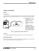
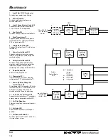
Page 26: ...scription Refer to the functional block diagram Figure 3 2 and the system wiring diagram Figure 3 4 Refer to Section 4 Parts List to locate and identify the system components described 2 1 1 Input Voltage Selector Switch 2 Retaining screw Remove screw and position switch to select required voltage Reinstall retaining screw and tighten to secure switch in place To use rated output see specification...

Page 27: ...rovides isolation from power circuitry Also contains power ready and trouble LEDs 9 Output Control R6 Selects cutting output level 10 Thermostat TP1 If unit overheats TP1 opens stopping cutting output TP1 is located inside T1 11 Power Up Delay Relay CR6 Input Resistor R2 During power up 2 3 seconds R2 limits inrush current to T1 CR6 shorts out R2 after power up delay and keeps R2 shorted out while...

Page 28: ...l Torch Cap Safety Circuit Torch Trigger Circuit Work Secondary Primary Fan Motor FM 115 or 230 VAC 4 5 6 7 12 1234 1234 1234 1234 1234 123456789012345 123456789012345 123456789012345 Pilot Electrode AC or DC Control Circuits 115 or 230 VAC 1 Φ Power Cutting and Pilot Current Circuits Figure 3 2 1 Functional Block Diagram 115 230 Volt To Torch Air Supply 115 VAC DC Power 7 98 ...

Page 29: ... Selects cutting output level 8 Thermostat TP1 If unit overheats TP1 opens stopping cutting output TP1 is located inside T1 9 Power Up Delay Relay CR6 Input Resistor R2 During power up 2 3 seconds R2 limits inrush current to T1 CR6 shorts out R2 after power up delay and keeps R2 shorted out while the unit is operating 10 Contactor Control Relay CR7 Connects main transformer T1 secondary output pow...

Page 30: ... Signal Command Signal Torch Cap Safety Circuit Torch Trigger Circuit Work Secondary Primary Fan Motor FM 3 2 4 5 10 1234 1234 1234 1234 12345678901234 12345678901234 12345678901234 Pilot Electrode AC or DC Control Circuits 1 Φ Power Cutting and Pilot Current Circuits Figure 3 2 2 Functional Block Diagram 200 Volt To Torch Air Supply 115 VAC DC Power 7 98 ...

Page 31: ...D Illuminates if the retaining cap is loose Turn power Off O and check that the retaining cap is tight Whenever the retaining cap shutdown system has been activated the power must turned Off O and then back On I to reset the sys tem If problems persist complete weekly checks listed under Routine Maintenance before performing trouble shooting OVER TEMP LED Illuminates if power supply overheats See ...

Page 32: ...ce worn consumables as necessary 1 2 Check for proper installation of swirl ring 1 3 Check for damaged torch or torch lead 1 4 Check air system for leaks 1 5 Check coil voltage and connections of control relay CR6 Check continuity of coil and condition of contacts Replace if necessary 1 6 Check coil voltage and connections of gas valve GS1 Check continuity of coil Replace if necessary 1 7 Check in...

Page 33: ...ace worn consumables as necessary 3 3 Check resistance and connections of input resistor R2 which is rated at 10 ohms 10 Replace if necessary 3 4 Check coil voltage and connections of contactor control relay CR7 Check continuity of coil and condition of contacts Replace if necessary 3 5 Check coil voltage and connections of control relay CR6 Check continuity of coil and condition of contacts Repla...

Page 34: ...for correct air pressure 7 2 Check for sufficient air supply pressure 7 3 Check air system for leaks 7 4 Check for dirty air filter regulator and clean if needed 8 1 Check torch retaining cap to ensure it is tight 8 2 Check for proper torch lead connections 8 3 Check safety control board PC2 and connections Replace if necessary 9 1 Thermostat TP1 is open overheating Allow the fan to operate the th...

Page 35: ... the power and unplug the cord or set the line disconnect switch to Off before servicing the unit or changing consumable parts In the U S use a lock out tag out procedure until the service or maintenance work is complete In other countries follow appropriate national or local safety procedures 7 98 ...

Page 36: ...rom receptacle before checking resistance R1 All values for T1 are less than 1 ohm Voltage Readings a Tolerance 10 unless specified b Reference to circuit common lead 43 unless noted V1 V2 V3 115 VAC V4 170 VAC V5 V6 V7 18 VAC V8 24 VAC V9 255 VDC open circuit voltage V10 22 5 VDC during pilot arc V11 12 VDC V12 V13 24 VDC V14 255 VDC open circuit voltage Figure 3 4 1 Wiring Diagram 115 230 Volt 7...

Page 37: ...rd or set the line disconnect switch to Off before servicing the unit or changing consumable parts In the U S use a lock out tag out procedure until the service or maintenance work is complete In other countries follow appropriate national or local safety procedures V4 V9 R1 V2 V8 V7 V5 V6 V1 7 98 ...

Page 38: ... ohm Voltage Readings a Tolerance 10 unless specified b Reference to circuit common lead 43 unless noted V1 115 VAC V2 200 VAC V4 170 VAC V5 V6 V7 18 VAC V8 24 VAC V9 265 VDC open circuit voltage V10 22 5 VDC during pilot arc V11 12 VDC V12 V13 24 VDC V14 265 VDC open circuit voltage Figure 3 4 2 Wiring Diagram 200 Volt V11 V12 V14 V10 Power Up Delay Relay Requires 40 PSI 2 8 bar to close S3 V13 7...

Page 39: ...To Base Ground 43A To Base Ground 4A 5A 5A 6A 7A 4C 6B 2B 2C 2D 27A 29A 28A To PC2 RC10 To T1 PLG23 36A 37A 35A 38A To Torch Cap Switch 35A 36A 37A 38A To Torch Trigger 1 2 3 4 3A 1A 2C 6A 7A 4C 2D 6B To Fan Motor 4C 4B 2B 2C 2D 6A 6B 2A 29A 4A 3A 2B 4A 29A 3A 5A 5A PLG10 7 98 ...

Page 40: ...3 17 Service Manual MAINTENANCE Figure 3 5 1 Wiring Harness Diagram 115 230 Volt 7 98 ...

Page 41: ...18 MAINTENANCE 7 98 To Power Cord 3A 1A 2B 4B 29A 3A 3A 4B 2B 29A S1 CR6 R2 27A 29A 28A 1A To Torch Cap Switch 38A 37A 35A 36A To Torch Trigger To PC2 RC10 36A 37A 35A 38A PLG10 43A To Base Ground PLG22 2B 4A LOAD LINE ...

Page 42: ... To SR1 Neg 10A 11A To R1 21A To R1 20A To Torch Pilot 25A To Torch Electrode 23A 23B To SR1 AC To 1T To CR1 22A 32A 32B 22A To Center Baffle Ground 43B 43B 20A 10A 11A 21A 24A 23A 25A PLG4 32B 32A To PC1 RC4 PLG6 To PC1 RC6 To S3 8A 9A To GS1 15A 14A To PC1 RC1 31A 30A 30A 17A 16A 19A 26A 31A 18A PLG1 To PC2 RC11 13A 26A 28A 8A 43A 14A 12A 15A 19A 17A 18A 16A 9A 27A PLG11 To CR7 12A 13A ...

Page 43: ...ve the torch main body and torch switch from the handle halves 3 Cut and remove the cinch strap Tyrap 4 Cut the 4 white wires connecting the torch lead to the plunger Cut the wires at the butt splice 5 Cut the 2 blue wires connecting the torch lead to the microswitch Cut the wires at the butt splices 6 Cut the 2 red wire connecting the torch lead to the pilot arc lead Cut the wire at the butt spli...

Page 44: ... 6 and perform the following procedure 1 Remove the 5 screws that secure the handle halves together 2 Remove the torch switch from the handle 3 Remove the torch switch by cutting the 2 splices at the torch lead violet wires 4 Replace the torch switch by crimping the switch wires and the violet wires from the torch lead together with the splices 5 Install the torch switch back into the handle While...

Page 45: ...max350 by following this basic troubleshooting guide or if you need further assistance 1 Call your distributor who will be able to help you or refer you to an authorized Hypertherm repair facility 2 Call Hypertherm Technical Service or the nearest Hypertherm office listed in the front of this manual 7 98 ...

Page 46: ...Service Manual 4 1 PARTS LIST Section 4 PARTS LIST In this section 115 230 Volt Power Supply 4 2 200 Volt Power Supply 4 4 PAC110 Torch Assembly and Leads 4 6 Consumable Parts 4 7 7 98 ...

Page 47: ...cuit card power control PC1 1 24 060003 Handle lifting 1 25 060002 Cover 1 26 060028 Box consumable storage 1 060027 Shelf consumable box storage 1 060029 Door consumable box storage 1 060030 Catch consumable storage 1 060031 Hinge consumable storage 1 27 060075 Switch toggle DPST 40A 600V S1 1 060034 Gasket switch 1 28 060076 Relay enclosed 12 VDC SPST CR6 1 29 060000 Case Section base back front...

Page 48: ... 1 1 115 230 Volt Powermax350 Power Supply 7 98 1 2 3 4 5 6 7 8 9 10 11 14 13 12 15 16 18 17 19 20 19 21 22 23 24 25 26 27 28 29 30 31 33 34 35 37 38 39 36 40 41 43 42 44 45 46 47 9 PAC110 Torch See Figure 4 2 32 fan mounted to blow inward ...

Page 49: ...ator edge trim 1 Bushing snap in 1 22 060019 Stand off 6 32 x 437 long 3 23 060040 Assembly circuit card power control PC1 1 24 060003 Handle lifting 1 25 060002 Cover 1 26 060028 Box consumable storage 1 060027 Shelf consumable box storage 1 060029 Door consumable box storage 1 060030 Catch consumable storage 1 060031 Hinge consumable storage 1 27 060075 Switch toggle DPST 40A 600V S1 1 060034 Ga...

Page 50: ...PARTS LIST Figure 4 1 2 200 Volt Powermax350 Power Supply 7 98 8 9 10 11 14 13 12 15 16 18 17 19 20 19 1 2 3 4 5 6 2 1 7 21 22 23 24 25 26 27 28 29 30 31 33 34 35 37 38 39 36 40 43 45 46 47 9 32 fan mounted to blow inward ...

Page 51: ...t 4 5 m Lead 070058 Torch Assembly with 25 ft 7 6 m Lead 1 001192 Handle PAC110 1 2 075339 Screws P S 4 X 1 2 PH RND S B 3 3 075341 Screws P S 4 X 3 4 PH RND S B 2 4 005094 Switch Torch Pushbutton 1 5 020588 Torch Main Body with Micro Switch PAC110 1 6 044016 O Ring BUNA 90 Duro 614X 070 1 7 029241 Torch Lead 15 ft 4 5 m 1 7 029257 Torch Lead 25 ft 7 6 m 1 1 7 6 5 2 3 4 1 2 ...

Page 52: ... parts are found in a box located in the left side of the power supply cover Figure 4 3 Consumable Parts 7 98 Index No Part No Description Quantity 1 020239 Ring Swirl 1 2 020382 Electrode Extended 1 3 120504 Nozzle Extended 25A 1 4 020218 Cap Retaining 1 3 2 1 4 ...

Reviews: