3-3
Service Manual
M
AINTENANCE
THEORY OF OPERATION
General
115/230 Volt Unit
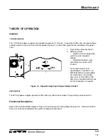
The 115/230 volt power supplies are shipped to operate at 115 volts. To operate at 230 volts, the input voltage
selector switch must be set to the 230V position (Figure 3-1) and a 230V plug must be installed on the power
cord.
200 Volt Unit
The 200 volt power supplies operate at 200 volts only and do not include an input voltage selector switch.
Functional Description
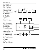
Refer to the functional block diagram, Figure 3-2 and the system wiring diagram Figure 3-4. Refer to Section 4,
Parts List, to locate and identify the system components described.
2
1
1
Input Voltage Selector Switch
2
Retaining screw
•
Remove screw and position
switch to select required
voltage.
•
Reinstall retaining screw
and tighten to secure switch
in place.
To use rated output (see
specifications in section 2), an
individual branch circuit capable
of carrying 33A, 115V at 35%
duty cycle; or 18A, 230V at 35
duty cycle and protected by fuses
or circuit breakers is required.
Figure 3-1 Repositioning Input Voltage Selector Switch
7-98


